Drag Chain Conveyor: Types, Capacity, Applications, and Selection Guide for Malaysian Industry
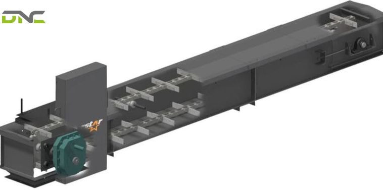
A drag chain conveyor moves bulk materials through an enclosed trough by pulling a chain fitted with flights (paddles) through the material bed. Unlike belt conveyors that carry material on top of a moving surface, drag chain conveyors immerse the chain directly in the material — dragging it from inlet to outlet at controlled, low speed. The enclosed trough contains dust, prevents spillage, and protects both the material and the surrounding environment.
In Malaysian industry, drag chain conveyors are the dominant choice for palm oil fresh fruit bunch (FFB) steriliser feeding, paddy and feed grain transfer at grain terminals, cement and clinker handling, and biomass fuel (EFB, wood chips) handling at power plants — applications where belt conveyors would spill, contaminate, or degrade the material.
How a Drag Chain Conveyor Works
The drag chain conveyor’s operating mechanism involves four components working in sequence:
Chain assembly: A continuous loop of steel chain runs along the bottom of an enclosed rectangular trough. Chain links are typically roller chain, cast chain, or forged chain — selected based on the abrasiveness and weight of the material conveyed.
Flights (paddles): Steel flights are attached transversely across the chain at regular intervals (the flight pitch). The flight height determines how much material is pushed per cycle; flight width matches the trough interior width with 5–10 mm clearance on each side.
Trough: The enclosed steel housing through which material and chain travel. The active (carrying) strand runs along the trough bottom; the return strand runs overhead in the same housing or in a separate return path. The enclosed design prevents dust emission and spillage — a key advantage over open belt conveyors for dusty materials (cement, grain, mineral powders).
Drive unit: A geared motor drives the head shaft and sprocket, pulling the chain through the trough. Speed is typically 0.1–0.5 m/s — much slower than belt conveyors (0.5–3.0 m/s). The slow speed minimises material degradation and reduces chain wear.
Material enters through an inlet opening in the trough top, accumulates ahead of the flights, and is dragged progressively to the outlet. Multiple inlets and outlets can be incorporated in a single trough — enabling collection from multiple sources or distribution to multiple destinations.

Drag Chain Conveyor Types
1. Single-Strand Paddle (Scraper) Conveyor
The simplest configuration — a single chain strand running centrally in the trough, with flights attached at intervals. Material is pushed by the flight face rather than carried en-masse.
Trough cross-section: Typically 200×200 mm to 600×400 mm (W×H).
Capacity: 5–100 m³/hour depending on flight size and speed.
Best for: Coarse, heavy materials that do not need gentle handling — ore fines, coal, mineral aggregate, ash, metal chips.
Limitation: Material contacts chain directly — not suitable for materials that are contaminated by metal contact (food ingredients, pharmaceutical powders).
2. Double-Strand Drag Conveyor
Two parallel chain strands run on either side of the trough, connected by flights spanning the full trough width. The wider flight provides better material engagement for heavy or poorly flowing materials.
Trough width: 400–1,200 mm. Load supported on two chains — higher capacity and better weight distribution.
Capacity: 20–500 m³/hour.
Best for: Heavy bulk materials (clinker, limestone, EFB, FFB sub-products), wide troughs where a single central chain would leave ungathered material at trough edges.
Malaysian application: Palm oil mills use double-strand conveyors for EFB (empty fruit bunch) transfer to biogas digesters and EFB pelletising lines. EFB is bulky, fibrous, and wet — double-strand provides reliable drag even with irregular EFB shape.
3. En-Masse Drag Conveyor
The en-masse design uses a single chain with skeletal (open) flights running centrally in a rectangular housing. Instead of pushing material with individual flight faces, the en-masse conveyor fills the housing cross-section with material — the bottom layer is moved by the chain, and inter-particle friction moves the mass above. Material fill of the housing cross-section reaches 80–90%, versus 40–50% for standard scraper conveyors.
Key advantage: En-masse conveyors use a smaller cross-section to achieve the same capacity as scraper conveyors — because they use nearly the full housing cross-section. A 300×300 mm en-masse housing may match the capacity of a 600×400 mm scraper trough.
Best for: Free-flowing granular materials with good inter-particle friction — grain (paddy, wheat, maize), pellets, seeds, dried coffee, animal feed. The gentle, rolling material movement minimises grain breakage — critical for high-grade paddy and coffee.
Limitation: Not suitable for sticky, high-moisture, or fibrous materials that bridge between flights and housing walls.
Malaysian application: Grain terminal operators at Port Klang and Johor Bahru use en-masse conveyors for rice, maize, and soybean unloading and distribution — throughput 100–500 m³/hour with minimal grain breakage.
4. Tubular Drag (Disc) Conveyor
A single chain with evenly spaced circular discs runs inside a round tube. The discs fit the tube internal diameter with close tolerance (5–10 mm clearance). Material fills the space between discs and is dragged axially through the tube.
Key feature: The tube can be routed in multiple directions — horizontal, vertical, inclined, and curved — in a single continuous run. Multi-directional routing in a single system eliminates transfer points between conveyors.
Capacity: Typically 1–50 m³/hour — lower than rectangular drag conveyors but with unique routing flexibility.
Best for: Fine powders, fragile materials, and materials requiring fully enclosed (leakproof) transfer — pharmaceutical powders, chemicals, food ingredients, pigments.
Malaysian application: Flour mills in Selangor use tubular drag conveyors to transfer flour from sifter discharge to mixing hoppers along multi-directional routed tube systems, eliminating dust emission and flour loss.

En-Masse vs. Paddle Drag Conveyor: Selection Comparison
| Parameter | Paddle (Scraper) | En-Masse |
| Material fill % | 40–50% | 80–90% |
| Material type | Coarse, heavy, abrasive | Free-flowing granular |
| Material degradation | Higher (flight impact) | Lower (mass flow) |
| Maximum incline | 25–35° | 15–20° (limits inter-particle shear) |
| Housing cross-section | Larger for same capacity | Smaller for same capacity |
| Maintenance | Higher chain wear | Lower — chain inside material, self-lubricated |
| Capacity range | 5–500 m³/hour | 20–400 m³/hour |
| Malaysian use case | Palm oil EFB, clinker, coal | Grain, pellets, seeds, feed |
Key Design Parameters
Chain Pitch
Chain pitch (the distance between chain links) determines:
- Flight spacing — typically 2–4× chain pitch
- Drive sprocket tooth engagement
- Maximum conveyor speed (high pitch + high speed = high inertia loads at start-up)
Standard roller chain pitches for drag conveyors: 75 mm, 100 mm, 150 mm, 200 mm. Forged chain pitches: 100–300 mm for heavy-duty applications.
Trough and Housing Sizing
Trough cross-section is calculated from required capacity:
Required cross-section area (A) = Throughput (m³/h) / (3,600 × conveyor speed (m/s) × fill factor)
Where fill factor = 0.45 for scraper conveyors; 0.80 for en-masse.
Example: 100 m³/h at 0.2 m/s, en-masse:
A = 100 / (3,600 × 0.2 × 0.80) = 0.174 m² → select 420×420 mm housing
Conveyor Speed
- Paddle/scraper: 0.1–0.5 m/s (higher speed for heavy, coarse materials)
- En-masse: 0.05–0.3 m/s (slower to maintain mass flow integrity)
- Tubular: 0.1–0.5 m/s
Excessive speed causes material turbulence (scraper), breakage (en-masse), or accelerated chain wear (all types).
Chain Pull Calculation
Total chain pull force = material drag force + return strand friction + chain and flight weight
Material drag force: F = L × (mass flow rate/speed) × μ
Where μ = friction coefficient between material and trough bottom (0.3–0.6 for most bulk materials).
Chain pull must not exceed the chain’s safe working load (typically: chain break load / 6 for normal operation; / 8 for shock-loading applications).

Drag Chain Conveyor Applications in Malaysia
Palm Oil Processing
Malaysia’s 451 palm oil mills process 77–80 million tonnes of FFB per year. Every mill uses drag chain conveyors for:
- FFB steriliser feeding: Double-strand conveyors loading FFB into horizontal sterilisers. High load (FFB bulk density 400–550 kg/m³), wet conditions, and fibrous material demand robust double-strand design with forged chain.
- EFB transfer: After threshing, EFB (empty fruit bunches) must be transported to EFB processing, biogas digesters, or composting areas. EFB is bulky (bulk density 100–150 kg/m³), fibrous, and wet — unsuitable for belt conveyors. Drag chain conveyors with wide flights handle EFB reliably.
- Kernel and fibre handling: Internal mill drag conveyors transfer pressed fibre and wet kernels between processing stages.
Cement and Building Materials
Cement plants at Ipoh, Kanthan, and Rawang use drag chain conveyors for:
- Clinker transfer from kiln outlet to clinker silo (high temperature — up to 150°C, requiring heat-resistant alloy chain and trough)
- Raw meal transfer between grinding and blending stages
- Cement powder transfer to bagging silos
Grain Handling (Ports and Feed Mills)
Malaysia imports 4–5 million tonnes of grain annually through Port Klang, Johor Bahru, and Penang. Grain terminal drag chain conveyors:
- En-masse conveyors for paddy, maize, soybean, wheat transfer from ship unloader to storage silos
- Sub-grain feed mills use paddle conveyors for finished pellet and mash transfer to bagging
Biomass and Power Generation
Malaysia’s 135+ biomass power plants (EFB, PKS, wood chips) use drag chain conveyors for fuel transfer:
- EFB pellet and chips transfer from storage to boiler feed hoppers
- Bottom ash removal from boiler grates (high temperature, abrasive — requiring hardened alloy steel construction)
Food Processing
Food-grade drag chain conveyors (stainless steel construction, food-safe chain lubricants, enclosed hygienic design) are used in:
- Sugar and salt transfer in food ingredient facilities
- Spent grain removal in F&N and Carlsberg breweries
- Dried ingredient transfer in Nestlé and Mondelēz processing

Drag Chain Conveyor Failure Modes and Prevention
Chain Stretch and Elongation
Cause: Normal wear at chain link pins and bushings. Each 0.1 mm of pin/bushing wear results in measurable chain elongation. In abrasive material environments (clinker, mineral fines), wear accelerates.
Symptom: Chain sag between sprockets; chain jumping on sprocket teeth; increased drive motor torque.
Prevention: Monthly chain elongation measurement (replace at 2–3% elongation from new); use sealed-for-life chain pins in abrasive environments; apply correct lubricant grade to chain at defined intervals.
Flight Wear
Cause: Abrasion of flight face and bottom edge by material flow and trough bottom contact. Hard, angular materials (clinker, quartz sand) cause rapid flight wear.
Symptom: Reduced material throughput; material spilling past worn flight edges; increased motor current (flight dragging on worn trough bottom).
Prevention: Select flight material hardness appropriate to material abrasiveness (AR400 or AR500 steel for highly abrasive materials); design flights with replaceable wear-face inserts; inspect flights at 2,000-hour intervals.
Trough Bottom Wear
Cause: Chain and material abrasion of trough bottom plate. Most concentrated at the active material zone between flights.
Prevention: Use replaceable wear liner plates (12–20 mm AR400) bolted to trough bottom; inspect and rotate liners every 6,000 hours.
Material Bridging and Blockage
Cause: Sticky, high-moisture, or cohesive materials (wet EFB, damp grain, sticky minerals) bridge between flights and trough walls, stalling the chain.
Prevention: Do not exceed specified moisture content for the material; specify trough vibration for sticky materials; install overload torque limiters to protect chain and drive from blockage.
Corrosion in Tropical Environments
In Malaysia’s high-humidity environment (85–95% RH average), standard mild steel drag conveyor components corrode rapidly when processing wet materials (FFB, EFB, food products):
Prevention: Hot-dip galvanised or epoxy-painted trough exterior; stainless steel 304 chain and flights for food and wet applications; weekly inspection of drain points to prevent water accumulation in trough.

Maintenance Schedule
Weekly: Inspect chain tension and sag; check flight condition for cracking or excessive wear; verify trough drain points are clear; check motor current vs. baseline.
Monthly: Measure chain elongation at 5 reference points; lubricate chain with specified lubricant; inspect sprocket teeth for wear (replace at 25% tooth profile reduction); check trough bolted joints for loosening due to vibration.
Quarterly: Full flight wear measurement; trough wear liner inspection and rotation; drive shaft alignment check; gearbox oil sample analysis.
Annual: Full chain replacement if elongation exceeds 2%; sprocket replacement; drive unit overhaul per OEM schedule.
Drag Chain Conveyor vs. Alternative Conveyor Types
| Conveyor Type | Best For | Not Suitable For |
| Drag chain | Enclosed bulk transfer, dusty/wet material | High-speed, long-distance transfer |
| Belt conveyor | Long distance, high speed, high capacity | Dusty/wet material without covers, severe inclines |
| Screw conveyor | Short distance, flowable material | Fragile material (breakage), long distances (high torque) |
| Bucket elevator | Vertical lifting | Horizontal transfer |
| Pneumatic | Fine powder, long distance | Dense, abrasive, wet material |
Choose drag chain when: material is dusty, wet, or must be fully enclosed; multiple inlets/outlets are needed; inclines are moderate (up to 35°); material degradation must be minimised; the environment requires dust-tight transport.
DNC Automation’s Drag Chain Conveyor Solutions
DNC Automation designs and supplies custom drag chain conveyor systems for Malaysian palm oil, food, cement, and industrial applications — from single-conveyor supply to complete bulk handling system integration.
Engineering scope:
- Capacity calculation and chain pull analysis for new installations
- Paddle, en-masse, and tubular configurations based on material properties
- Material-specific construction: carbon steel for industrial; SS304/316 for food; alloy AR400 for abrasive
- Siemens PLC control with overload protection, speed monitoring, and blockage detection
- Modular trough construction for on-site assembly in confined spaces
Malaysian industry experience: DNC has supplied drag chain conveyor systems for palm oil mills (FFB and EFB handling), grain terminal operators, cement handling facilities, and food processing plants — with documented operational track records across Malaysia’s major industrial regions.
MIDA SAG eligibility: Drag chain conveyor systems installed as part of automated bulk material handling upgrades qualify for MIDA’s Strategic Automation Grant (up to RM 1 million, 50% of qualifying capital expenditure).
Contact DNC Automation to discuss your drag chain conveyor specification — including material data sheet review, capacity calculation, and layout optimisation.
- 149 views
- 0 Comment
Recent Comments