Conveyor Trolley: Types, Load Ratings, Maintenance, and Overhead System Design Guide
A conveyor trolley is the wheeled carriage unit that runs along the track of an overhead conveyor system, supporting the product load and transmitting motion from the drive chain or power rail. Every overhead conveyor — whether a simple monorail system in a warehouse, a power-and-free line in an automotive paint shop, or an enclosed track conveyor in a food facility — depends on properly selected and maintained trolleys to achieve design load capacity, speed, and service life.
In Malaysian manufacturing, conveyor trolleys are most visible in automotive OEM paint lines (Toyota Shah Alam, Proton Tanjung Malim, DRB-Hicom Pekan), glove manufacturing dipping lines (Hartalega, Top Glove, Supermax), and heavy industrial assembly operations — where thousands of trolleys cycle continuously through production environments 24 hours a day, 5–7 days a week.
This guide covers trolley types, load calculation methodology, track specifications, maintenance schedules, failure modes, and selection criteria for Malaysian engineers and production managers.
What Is a Conveyor Trolley and How Does It Function
A conveyor trolley consists of:
Load wheel assembly — Two to four wheels that run on the inside flanges of a structural track (I-beam, C-channel, or enclosed tube). Wheels are typically steel, cast iron, or nylon-over-steel for different load and noise requirements.
Frame/body — Stamped steel, fabricated steel, or cast iron frame connecting the wheels. The frame transmits vertical load from the hanging product to the wheels and horizontal forces (from chain pull or track curves) through the wheel flanges.
Load bar or attachment — A hook, bar, pin, or custom bracket attached below the frame to carry the product. Load bars can be fixed (constant orientation) or swivel (product can rotate) depending on process requirements.
Chain attachment — A pusher dog, drive dog, or carrier attachment connects the trolley to the overhead chain, transmitting drive force. In power-and-free systems, the trolley can be decoupled from the chain to accumulate (stop and wait) without stopping the chain.
The trolley’s fundamental function is to convert chain linear motion into product transport while managing the load’s weight through the wheel-track contact and maintaining product orientation through the attachment geometry.

What Are the Main Components of a Conveyor Trolley System?
Conveyor Trolley Types
1. Standard Pushed Trolley (Plain Trolley)
The simplest type — a trolley pushed by a chain via a pusher dog. The trolley has no independent drive. When the chain moves, trolleys move. When the chain stops, everything stops.
Wheel configuration: 2-wheel for light loads (<50 kg); 4-wheel for medium loads (50–200 kg).
Track type: Steel I-beam (75×75, 100×100, 150×150 mm) or patented track sections.
Applications: Paint rack conveying, parts washing, warehousing, simple assembly lines where all stations run simultaneously.
Limitation: No accumulation. One zone stop = entire conveyor stops.
2. Free Trolley (Power-and-Free System)
In power-and-free overhead conveyors, the chain (power track) runs continuously above a separate free track. A carrier — typically a pair of front and rear trolleys on the free track connected by a load bar — is engaged or disengaged from the chain by a pusher dog.
When the pusher dog engages the carrier’s drive dog: the carrier moves with the chain.
When a stop is raised: the pusher dog disengages, the carrier accumulates while the chain continues.
Key capability: Accumulation — products queue at stations without stopping the drive chain. Enables: process stations with variable cycle times, buffer accumulation before spray booths, and route switching at switches/transfers.
Load capacity: Standard P&F trolleys: 150–500 kg per carrier. Heavy-duty P&F for engine and body assembly: 2,000–5,000 kg.
Malaysian automotive application: Toyota’s Shah Alam paint line uses P&F conveyors to buffer vehicle bodies before entry to prep booth, primer booth, and topcoat booth — each with different cycle times. Bodies accumulate without disrupting line speed.
3. Enclosed Track Trolley
The I-beam is replaced by a hollow structural tube (typically 3″ or 4″ enclosed track). Trolleys with internal wheels run inside the tube, with the load bar extending through a slot in the bottom flange.
Advantages over open I-beam:
- Dust and debris exclusion — wheels run in clean enclosed environment
- Higher stiffness per unit weight — same load capacity with lighter structure
- Cleaner appearance — used in food, pharmaceutical, and retail environments
Load capacity: Typically 50–500 kg per trolley depending on track size.
Malaysian food industry application: Frozen chicken processing facilities in Selangor use enclosed track conveyors over production lines — IP-rated enclosed wheels prevent contamination from overhead trolley wear debris falling onto product below.
4. Monorail Trolley (Workstation Crane Trolley)
Individual trolleys running on a single overhead beam (I-beam or box section) for point-to-point load movement within a work cell — as in a manual workstation crane, jib crane, or bridge crane runway.
Wheel type: Hardened steel wheels with flanges for I-beam; polyurethane-tread wheels for noise-critical environments.
Load range: 100 kg to 50,000 kg depending on beam size and wheel rating.
Differentiation from conveyor trolley: Monorail workstation trolleys move on demand (manual push or electric hoist drive) rather than continuous chain drive. However, the trolley component — wheel, frame, attachment — is functionally the same.
5. Inverted Overhead Trolley (Underhung)
Some configurations mount trolleys below a ceiling-mounted beam track, with product suspended beneath — this is the standard overhead conveyor configuration.
In contrast, floor-level power rail systems (electrified monorail systems, or EMS) use trolleys that travel on elevated or floor-level rails with on-board drive motors, picking power from electrified bus bars. These carry automotive bodies between body shop, paint shop, and trim-and-chassis assembly. Load capacity: up to 5,000 kg per carrier.

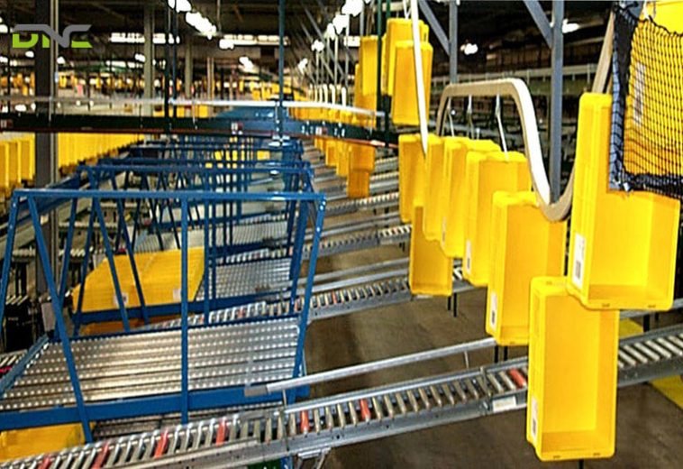
Conveyor trolley systems are widely used across industries due to their flexibility and load-handling capability
Conveyor Trolley Load Calculation
Correct trolley selection requires calculating the actual load per trolley and comparing it against the trolley’s rated working load limit (WLL) with appropriate safety factor.
Step 1: Calculate Total Carrier Load
Total load = product weight + load bar weight + attachments
Example: Vehicle body (600 kg) + load bar (80 kg) + hooks (20 kg) = 700 kg total load.
Step 2: Determine Trolleys per Carrier
A standard P&F carrier uses 2 trolleys (front and rear). Each trolley carries approximately 50% of carrier load in straight sections, but up to 60–70% of load during acceleration and deceleration.
Load per trolley (dynamic) = total load × 0.7 / number of trolleys
= 700 kg × 0.7 / 2 = 245 kg per trolley
Step 3: Apply Safety Factor
Standard safety factor for overhead conveyor trolleys: 4:1 (WLL = breaking load / 4).
Required WLL per trolley = 245 kg × 1.5 (dynamic factor for curve and acceleration) = 368 kg.
Select next standard trolley WLL above 368 kg — typically 500 kg class.
Step 4: Verify Wheel Contact Stress
At maximum rated load, the Hertzian contact stress between the wheel and track flange must remain below the material’s yield strength. This calculation is typically provided in the trolley manufacturer’s load tables — verify the selected wheel diameter and hardness meet the requirement at calculated load.
Step 5: Chain Pull Verification
The total chain pull force = Σ(load × friction coefficient) across all loaded trolleys on the conveyor. The chain pull must not exceed the chain’s rated working load at the drive sprocket. For long conveyors or heavy loads, intermediate drives reduce chain tension.

Limitations of Conveyor Trolley Systems
Track Specifications for Conveyor Trolleys
Standard I-Beam Track
Carbon steel I-beams (Grade 250 or Grade 350) with precision-milled top flange running surfaces. Standard I-beam sizes: 3″ (75 mm), 4″ (100 mm), 6″ (150 mm) web height.
Running surface hardness: For steel wheels, minimum Brinell 180 HB on the track flange. For nylon-wheel trolleys, standard rolling surface finish (Ra 3.2) is sufficient.
Maximum deflection: Track between supports should deflect no more than span/500 at maximum load — typically limits support spacing to 1.5–3.0 m depending on beam size and load.
Track Curves
Horizontal curves (plan view turns): Minimum radius 900 mm for standard trolleys; 600 mm for short-wheelbase trolleys. Tighter radii increase flange wear and chain side loads.
Vertical curves (inclines/declines): Maximum grade typically 30° for powered P&F systems; 20° for gravity-return segments. Vertical curves must have minimum radius 1,200 mm to prevent chain binding.
Track Switches (P&F Systems)
Track switches route carriers from one track to another — for process routing, spur loading, or return loops. Pneumatic-actuated switches operate in <0.5 seconds. Safety interlock ensures switch is fully set before chain advances a carrier through.
Overhead Conveyor Trolley Maintenance
Proper trolley maintenance is the single biggest factor in overhead conveyor service life. A trolley with failed wheels can damage track flanges, causing cascading wear that requires full track replacement — a RM 200,000–500,000+ job on a large paint line.
Daily Checks
- Visual inspection for trolleys with damaged or seized wheels (look for flat spots, scoring, or wheels not rotating)
- Lubrication check at automatic chain oilers — confirm oil delivery to chain links
- Listen for abnormal noise: squealing (dry wheels), clunking (damaged wheel or bent frame), grinding (contamination in wheel bearing)
Weekly Maintenance
- Hand-check every 50th trolley for wheel rotation — spin each wheel to confirm bearing integrity
- Inspect all load bars and attachments for cracks, deformation, or loose pins
- Check pusher dogs and drive dogs for wear — replace pusher dogs at 30% face wear
- Measure track wear at highest-load sections using a hardness tester or caliper — track replacement threshold: 1.5 mm flange wear
Monthly Maintenance
- Full trolley inventory audit — count trolleys, confirm no missing or stranded trolleys
- Lubricate all trolley pivot points and chain attachment pins
- Inspect all track joints for step misalignment exceeding 0.3 mm
- Check switch actuators and verify correct routing for all program routes
- Review tension take-up position — chain elongation requiring take-up adjustment indicates approach to replacement interval
Annual Overhaul
- Replace all wheels reaching rated wear life (typically 3–5 years at 2-shift operation)
- Replace all chain beyond 3% elongation from new
- Replace all pusher dogs and drive dogs showing >50% wear
- Structural inspection of track hangers, support brackets, and building attachment points — check for corrosion, cracking, or elongated bolt holes
- Full load test after reassembly per original design specification

Selecting the right conveyor trolley system requires careful evaluation of both mechanical and operational factors
Overhead Conveyor Trolley Failures and Root Causes
Seized Wheel
Cause: Bearing contamination (paint overspray, chemical splash, water ingress), insufficient lubrication, overload beyond wheel WLL.
Effect: Dragging trolley scores the track flange. A single seized wheel on a 200-trolley system can gouge the track to unusability in 8–16 hours if not detected.
Prevention: IP67 sealed bearings for paint shop trolleys, automatic chain lubrication, load audit to confirm no overloading.
Bent or Cracked Frame
Cause: Impact (carrier collision with a stop or another carrier), shock load during product loading, fatigue from cyclic overload.
Effect: Misalignment causes uneven wheel loading, accelerating both wheel and track wear.
Prevention: Safety stops with shock absorbers to limit impact force, overload detection at loading stations.
Drive Dog Wear
Cause: Normal wear from repeated engagement with pusher dogs, accelerated by contamination or inadequate lubrication of contact surfaces.
Effect: Pusher dog misses drive dog — carrier fails to advance, blocking downstream flow.
Prevention: Replace drive dogs at 50% wear using regular visual inspection. Colour-coding by installation date enables systematic replacement.
Chain Jump at Track Curves
Cause: Excessive chain tension on tight horizontal curves, worn horizontal wheel flanges reducing lateral constraint, incorrect chain sag adjustment.
Effect: Chain derails from drive track, halting the entire system.
Prevention: Verify chain tension is within specification, inspect horizontal guide wheels on all P&F trolleys at tight curves, adjust chain catenary regularly.

Overhead Conveyor Trolley Failures and Root Causes
Overhead Conveyor System ROI for Malaysian Manufacturers
Overhead conveyor systems with trolley-based carriers deliver measurable ROI versus floor-based conveying or manual material movement in high-value processing environments:
Floor space recovery: Moving product flow overhead frees floor space for production equipment. In a typical automotive sub-assembly plant, shifting body transport overhead recovers 200–400 m² of floor area — equivalent to 2–4 production cells.
Labour displacement: A 200-carrier overhead P&F system replaces 8–12 material handlers in continuous operation — at Malaysian manufacturing wages (RM 2,000–3,500/month), the annual saving is RM 192,000–504,000. System payback period: typically 3–5 years.
Quality improvement: Overhead transport of bodies, components, or products through paint, coating, or dipping processes eliminates floor contamination transfer. Hartalega’s glove dipping lines use overhead trolley conveyors to carry formers through coagulant, latex, and leaching tanks — a process impossible with floor conveyors.
MIDA SAG eligibility: Capital investment in overhead conveyor systems — including trolleys, track, drives, controls, and integration — qualifies for MIDA’s Strategic Automation Grant (SAG) of up to RM 1 million (50% of qualifying capital expenditure). This significantly improves project ROI for Malaysian manufacturers.
Conveyor Trolley Applications in Malaysia
Automotive Paint Lines
Toyota Shah Alam, Perodua Rawang, Proton Tanjung Malim, and Honda Pegoh all operate overhead P&F conveyor systems for body-in-white transport through cleaning, phosphating, electrocoating (E-coat), primer, topcoat, and inspection. Typical line: 400–800 trolleys, 200–300 carriers, 600 kg carrier load, operating at 3–6 m/min.
Glove Manufacturing (Dipping Lines)
Malaysia produces 65–70% of the world’s rubber gloves. The dipping process — former enters coagulant tank, latex tank, leaching tank, stripping — is fundamentally an overhead trolley conveyor. Trolley systems for glove dipping use:
- Nylon or stainless steel wheels (chemically resistant to latex and coagulant)
- 316L stainless steel tracks and frames
- 50–150 kg load per trolley (former carrier with 200–400 former pins)
- Conveyor speeds: 0.5–2.0 m/min through latex tanks
Heavy Assembly and Warehousing
Johor’s industrial zones (Pasir Gudang, Tanjung Pelepas) use overhead monorail and P&F systems in heavy machinery assembly, shipbuilding support facilities, and regional distribution centres for order picking and sortation.
Why DNC Automation for Overhead Conveyor and Trolley Systems
DNC Automation engineers complete overhead conveyor systems — from trolley and track selection through drive engineering, PLC control integration, and commissioning — for Malaysian manufacturers requiring reliable, certified solutions.
Technical capabilities:
- P&F system design for automotive paint lines (up to 500 kg carrier load)
- Enclosed track conveyors for food and pharmaceutical environments
- EMS (Electrified Monorail Systems) for heavy automotive body transport
- Retrofit and upgrade of existing overhead systems — trolley replacement, track renewal, control modernisation with Siemens S7-1500 PLC and TIA Portal
Malaysia-specific expertise: DNC’s engineering team understands the specific requirements of Malaysian manufacturing under DOSH (Department of Occupational Safety and Health) regulations — including overhead conveyor design approval (Form D), load testing certification, and periodic inspection compliance.
Project experience: DNC has delivered overhead conveyor systems for Tier-1 automotive suppliers in Shah Alam and Selangor, food processing facilities in Johor, and electronics manufacturers in Penang — with documented availability rates exceeding 97% in the first year of operation.
Contact DNC Automation for overhead conveyor trolley system design, supply, installation, and maintenance in Malaysia.
Summary
Conveyor trolleys are the critical load-bearing and motion-transmitting components of overhead conveyor systems. The choice between plain, P&F, enclosed track, and monorail trolleys depends on required accumulation capability, load, environment, and track geometry. Proper load calculation, material selection for wheel and frame, and structured maintenance — particularly wheel inspection and bearing replacement — are the primary determinants of system reliability and total cost of ownership. For Malaysian automotive, glove manufacturing, and industrial assembly applications, overhead conveyor systems with properly specified trolleys deliver floor space, labour, and quality benefits that justify 3–5 year payback periods.
- 176 views
- 0 Comment
Recent Comments