


Warehouse Layout Design for Automation (Aisles, Flow, AGV Paths)
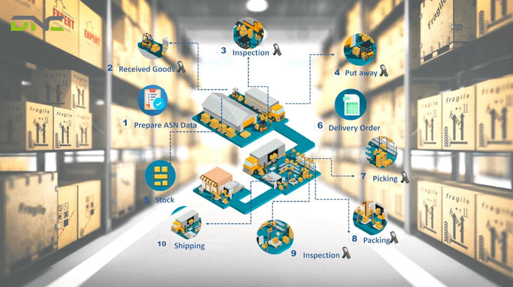
Warehouse layout design for automation is the plan that fixes where goods enter, travel, wait and leave before any storage block is drawn, because automated guided vehicles (AGVs), autonomous mobile robots (AMRs) and AS/RS (automated storage and retrieval system) cranes only work on planned paths.
The flow shape comes first. A U-shaped, I-shaped or L-shaped flow decides whether automated guided vehicle routes run one-way or cross at the dock face. Aisles then split into storage aisles, kept narrow for density, and transport paths, kept clear for flow.
The floor is specified per vehicle class, dock doors are counted from truck-handling hours, and floor space is sized for the peak month rather than the average. In a Malaysian manufacturer’s facility, the warehouse layout starts where the end-of-line hands over a wrapped pallet. DNC Automation engineers these conveyor and AGV interfaces for factories across Malaysia.
What Is Warehouse Layout Design for Automation?
Warehouse layout design for an automated facility is the arrangement of receiving, storage, picking, dispatch and support areas around a material flow that machines, not people, carry out. A conventional warehouse layout tolerates improvisation, because a forklift driver reroutes around a blocked aisle. An automated route does not improvise. Every path, transfer point and charging position has to exist on the drawing before commissioning. Warehouse managers read a layout as storage positions; automation engineers read it as a path network.
The functional areas of a warehouse layout are listed below, following the six-area division used in storage-industry design manuals.
- Loading and unloading area — docks, levellers and truck access.
- Reception area — quality check, sorting and label generation.
- Storage area — floor stacks, racking or AS/RS cranes.
- Picking area — integrated into storage or separated as a pick module.
- Dispatch area — packing, staging and outbound loading.
- Service area — offices, rest rooms and the battery charging area.
The Association of Southeast Asian Nations (ASEAN) logistics training curriculum lists five factors that shape any warehouse layout: product, space, equipment, circulation of goods and personnel. Automation changes the weight of those factors. Equipment and circulation stop being consequences of the building and become its starting point. Established warehouse design practice states the same principle as a design order: a warehouse is designed from the inside out, with the materials handling system drawn before the building.
That design order is the practical difference between a storage plan and an automated warehouse design. A facility that chooses its racking first and asks where the vehicles fit afterwards usually finds the paths too narrow, the crossings too many and the charging points in the wrong corner. An engineering-grade partner for warehouse automation in Malaysia starts the drawing from the vehicle route and the transfer points, then fills the remaining floor with storage.
The vehicle route through the warehouse is shaped by one early decision: where goods enter the building relative to where they leave it.

What Is Warehouse Layout Design for Automation?
Which Flow Shape Suits an Automated Warehouse: U, I or L?
The flow shape that suits an automated warehouse is the one whose dock arrangement produces the fewest vehicle crossings for the pallet rate the facility handles, and each of the three standard shapes trades crossings, travel distance and floor area differently in terms of automated vehicle traffic. Storage-industry sources agree on the dock placement behind each shape. They do not map any of the three shapes to vehicle paths.
The table below compares the three flow shapes on dock position, stock placement and the consequence for automated vehicles.
| Flow shape | Dock position | Fast-moving stock sits | Documented strength | Documented limit | Consequence for automated vehicles |
| U-shaped | Receiving and dispatch on the same side | Closest to the loading bays | Shared dock doors, cross-docking, put-away and retrieval trips combined, most economical land use | Shared dock area bottlenecks at peak hours | Inbound and outbound paths converge on one dock apron; paired trips cut empty travel |
| I-shaped (through flow) | Receiving and dispatch at opposite ends | In the centre of the building | Separate in and out, suits different inbound and outbound vehicles, suits a building connected to a production plant | Goods travel the full building length; needs a hard stand at each end | One-way loop with no crossing; every unpaired return leg runs the full length |
| L-shaped | Receiving and dispatch on adjacent walls | Between the two dock zones, extending to the rear | Better in/out separation than U, less cross-traffic | Extra floor for the angle; poor picking paths without planning | One turn node between the two dock walls; path length between U and I |
The U-shaped layout is the most common warehouse flow, and the regional logistics curriculum credits it with excellent lift-truck utilisation because put-away and retrieval trips are readily combined into one round trip. That advantage transfers to automated vehicles. Its cost is congestion: one dock face carries both directions of traffic.
Through-flow earns its extra land on high-volume, one-directional operations. The same curriculum names one application that matters to manufacturers — a warehouse connected to a production plant, where goods arrive from the line at one end and leave by truck at the other. The documented penalty is distance. Even the fastest-moving goods travel the full length.
Two or three shapes can also coexist in one building. In a factory warehouse, for example, finished pallets follow a through-flow from the plant end while packaging materials arrive and leave through shared docks. Each shape then produces its own pattern of vehicle routes.
How Does the Flow Shape Set the AGV Path Network?
The flow shape sets the AGV path network by fixing how many directions of traffic share each corridor and how many times loaded and empty vehicles cross in an automated warehouse. Two principles from the research on warehouse layout decide the network. The ASEAN curriculum requires that work lanes and transport lanes never cross. The standard flow rule of warehouse design requires one-way movement — straight, clockwise, counter-clockwise, up or down — and gives free movement priority over storage capacity.
Automated guided vehicles turn those principles into geometry. On a through-flow layout, a one-way loop runs down one side of the building and back along the other, with no head-on conflict and no crossing.
The loop has a price. Every automated guided vehicle that delivers a pallet to dispatch returns along the loop, and without a second task that return is empty and runs the full building length. On a U-shaped layout, both directions meet at the dock apron, which becomes a crossing node that the scheduling system has to arbitrate. In exchange, a vehicle that drops an inbound pallet into storage collects an outbound pallet on the same trip.
Crossings are managed by software and sensors rather than by drivers. DNC Automation’s EAGV-series vehicles position to ±10 mm or ±5 mm, detect obstacles with laser, mechanical and 3D binocular camera anti-collision systems, and receive routes from an AGV scheduling system over a wireless network linked to MES or WMS. Scheduling resolves a crossing. It does not remove the waiting time at it, which is why the number of crossing nodes belongs in the layout comparison. For automated vehicle types, DNC’s range of AGV and AMR platforms lists the EAGV-series vehicles and the SLAM chassis.
Route length also sets fleet size. At 80 pallets per hour, one pallet leaves every 45 seconds, and a vehicle running at 1.7 m/s (5.6 ft/s) covers at most about 38 m (125 ft) one way in that window — a lower bound this site derived that excludes transfer, acceleration and charging time. Longer loops need more vehicles. Loop length is measured between the points where loads change carrier, so those transfer points are the next element of the path network.
Transfer Points: Where Conveyor, Crane and Vehicle Meet
Transfer points are the fixed positions where a load changes carrier, and an automated warehouse layout has three recurring types. An AS/RS works on a fixed path and picks each pallet up at an I/O (input/output) station before the storage-retrieval machine stows it at a software-assigned location. A very narrow aisle (VNA) system usually requires P&D (pick-up and deposit) stations where counterbalance trucks or AGVs hand pallets to the VNA truck. An end-of-line pick-up station is where a conveyor releases a stretch-wrapped pallet to a vehicle.
Each station needs clear approach space on the vehicle side, so transfer points are placed on the path network before storage blocks are. When DNC’s engineers lay out an automated route, the first drawing shows only docks, the end-of-line pick-up station, transfer points and charging positions; storage blocks are added on a second pass. Charging positions are the other fixed stop on that first drawing.
Charging Positions: Keeping Energy Off the Main Loop
Charging positions belong off the main transport loop, in an isolated and ventilated area, the same requirement storage manuals set for recharging battery-powered handling equipment. DNC’s SLAM chassis supports intelligent charging, which makes the charger a station the vehicle drives to, and that station needs its own place on the path network. A charger placed on the main loop turns every charging stop into a blockage for the vehicles behind it.
Once the path network and its stations are fixed, the space left between them becomes aisles, and aisle width depends on which machine works each one.
Charging Positions: Keeping Energy Off the Main Loop
How Wide Should Aisles Be for Automated Equipment?
Aisle width for automated equipment is set by the vehicle or crane that works the aisle, not by the storage system beside it, and the answer differs for storage aisles and transport aisles. The curriculum’s principle “keep aisle space to a minimum” and the consultancy’s warning against trading aisles for storage look contradictory. They describe two different aisles.
Storage aisles are minimised for density. Mobile racking needs only one floating aisle per row and saves up to 50% of floor space, according to the curriculum’s comparison of storage modes, at the price of slow operation. Double-deep storage raises density by 30-40% but needs a double-deep reach truck and gives direct access to only half the locations. Racking is the context here, not the product: the storage mode decides which vehicle can serve it.
Transport aisles are protected for flow. The table below lists the width driver for each class of equipment that works an automated or semi-automated warehouse.
| Equipment class | What sets the aisle | Published figure in the research |
| Narrow-aisle reach truck | Truck and load dimensions per truck specification | Minimum 2.8 m |
| VNA truck or stacker crane | Guided vehicle width; rail or wire guidance | No aisle value; P&D stations and very high quality floor required |
| AS/RS storage-retrieval machine | Fixed path of the crane | Aisle belongs to the machine; I/O station at the end |
| AGV or AMR | Vehicle, load and safety-field dimensions | No universal value — specified per vehicle and per ISO 3691-4 operating zone |
A narrow-aisle reach truck needs a minimum of 2.8 m (9.2 ft) of aisle. Automated vehicles have no single published figure, and a quoted “standard AGV aisle” deserves suspicion. ISO 3691-4 (current edition 2023), the safety standard for driverless industrial trucks, covers AGVs, AMRs, tuggers and under-cart vehicles, and it states that the condition of the operating zone has a significant effect on safe operation; its Annex A specifies how that zone is prepared. The aisle is part of the operating zone. Its width follows the vehicle’s safety field, not a rule of thumb.
Width is only one dimension of the operating zone; the surface the vehicle drives on is the other.
What Floor Does an Automated Layout Need?
An automated layout needs a floor specified to the tightest vehicle class that will drive on it, because driverless and guided vehicles publish floor tolerances in different forms for different equipment types. The two published figures in the research measure different things. Treating them as one number is a specification error.
The ASEAN curriculum shows a super flat floor with a tolerance of 1 mm in 1,000 mm (0.1%, a gradient) for stacker cranes and VNA trucks. DNC’s SLAM (simultaneous localisation and mapping) mobile chassis is suited to floors with flatness within ±10 mm (0.39 in), a band of deviation rather than a slope. A building that serves both a VNA aisle and an AMR route therefore carries two floor specifications, zoned on the drawing.
Automated warehouse design fixes floor zones at the same time as the path network, for a reason of sequence. Correcting a finished slab under installed storage means stopping that zone; specifying the tolerance before the slab is poured does not. ISO 3691-4 treats the condition of the operating zone as a safety matter and specifies its preparation in Annex A. The layout drawing is where the floor part of that preparation becomes a measurable line.
Floor, aisle and path decisions complete the internal geometry of the layout.
Summary: What Have Flow, Paths and Aisles Fixed So Far?
Flow, paths and aisles have so far fixed four warehouse layout decisions, in this order. The flow shape comes first: through-flow gives automated vehicles a one-way loop with long empty returns, U-flow concentrates traffic on one dock face but pairs trips, and L-flow adds one turn node. The path network and its transfer points — AS/RS I/O stations, P&D stations and end-of-line pick-up stations — are drawn next, with charging kept off the main loop.
Aisles then split into storage aisles, minimised for density, and transport aisles, protected for flow and sized to each vehicle’s operating zone. The floor is zoned last, to the tightest vehicle that drives each zone. The remaining decisions size the building around that geometry.
How Many Docks and How Much Space Does the Layout Need?
At the planning stage, the docks and space a warehouse layout needs are calculated from peak handling hours and peak inventory volume, never from annual averages. The design consultancy states the rule directly: a warehouse designed on averages is right half the time and wrong the other half.
Dock count follows truck-handling time. The regional curriculum’s worked example runs as follows.
- A dock works 8 hours per day.
- Unloading one TEU (twenty-foot equivalent unit) container takes 1.6 hours.
- One dock therefore handles 8 ÷ 1.6 = 5 TEU per day.
- A facility receiving 20 TEU per day needs 20 ÷ 5 = 4 dock doors.
Too few goods-in doors create receiving bottlenecks that also delay suppliers’ trucks. Too many add construction cost without adding throughput. In a U-shaped layout, the same doors serve dispatch, so the calculation adds outbound truck hours to inbound ones.
Floor space follows peak inventory. The same curriculum’s seasonal example shows average inventory ranging from 3,000 m³ (about 105,900 ft³) in April to 10,000 m³ (about 353,100 ft³) in November — more than three times the low month. The annual mean of that table is 5,750 m³, and a warehouse layout sized to it would overflow in 4 of the 12 months. One automated-storage vendor recommends a 20-30% space allowance for growth and seasonal peaks, and the consultancy adds that a warehouse never runs at 100% of physical capacity because working space is part of capacity.
Automation changes one part of that sizing. In the automated section, the crane or AS/RS finds each stock location, so storage slots can follow density rather than walking distance. Slot placement still matters wherever people pick.
For a manufacturer’s warehouse, one inbound flow arrives without a truck at all: the production line.
How Many Docks and How Much Space Does the Layout Need?
Where Does the Warehouse Layout Meet the Production Line?
In a manufacturer’s warehouse, the warehouse layout meets the production line at the point where the end-of-line hands a finished unit load to the storage flow, and that handover decides the flow shape before any dock is placed. The regional logistics curriculum lists the connection to a production plant as a reason to choose through-flow: finished goods enter at the plant end and leave at the dock end, and the fast movers sit in the middle.
The handover point itself has a defined position on this site. The fixed conveyor owns the stretch where the palletizer sets the cadence and the load is still being contained — palletizer discharge, stretch wrapper and an accumulation pick-up station sized to the gap between vehicle arrivals. The automated vehicle takes over only after containment. A vehicle accelerates and brakes the pallet; a pallet conveyor moves it at a steady speed. DNC’s pallet conveyor system carries loads up to 1,500 kg (3,307 lb) at 5-30 m/min (16-98 ft/min) on 1,200 × 800 mm and 1,200 × 1,200 mm pallets, which makes the pick-up station a known, repeatable transfer point for the path network.
From that station, the layout continues with either vehicles or fixed conveying. Long fixed routes with steady rates favour conveyor runs, and DNC’s guide to warehouse conveyor systems covers inbound and outbound conveyor flows around an AS/RS. Shared, variable routes favour vehicles. In the layout this boundary implies, the conveyor stays inside the packing hall and vehicles cross the storage floor.
That interface is where layout errors surface, because a mistake on either side of the pick-up station shows up as waiting on the other side.
Which Layout Mistakes Stop Automation from Paying Back?
The layout mistakes that stop automation from paying back in automated projects are fixed obstacles on the path network, sizing on averages, excess handling touches and aisles specified for the wrong vehicle. Each one adds travel or waiting that no scheduling software removes later.
One warehouse design consultancy documents a case that shows the first mistake. A global brewer built two almost identical distribution centres. One team placed a cold store — about one-fifth of the footprint — in a corner with one door. The other placed it in the centre with doors at both ends, facing receiving and dispatch.
As cold-stored volumes declined, the central cold store became an immovable obstacle. Every pick and put-away trip detoured around it, so the site staffed more people than its twin and ran two air dams instead of one. An automated route around the same obstacle costs vehicle-hours instead of labour-hours.
The remaining layout mistakes follow a similar pattern. They are listed below with the evidence behind each.
- Sizing on averages — the 3,000-10,000 m³ seasonal swing shows why an average-sized floor overflows.
- Excess touches — non-automated warehouses handle goods 7-8 times on average; reducing that to 3-4 improves performance.
- Aisles for the wrong vehicle — too narrow raises collision and damage risk, too wide wastes floor.
- Automation where volumes do not justify it — an AS/RS installed where conventional storage suffices is waste, and ignoring volumes that justify automation is the opposite error.
Each of these mistakes is fixed at the drawing stage for the price of a revision. With Malaysian manufacturers facing structural labour shortages and the National Industrial Master Plan 2030 (NIMP 2030) pushing Industry 4.0 adoption, a layout that forces extra vehicles or extra staff erodes the labour savings automation was bought for. A payback window of 2-4 years for mid-volume Malaysian AS/RS projects assumes a layout that does not waste travel.

Which Layout Mistakes Stop Automation from Paying Back?
What Do Plant Engineers Ask About Automated Warehouse Design?
Plant engineers ask the questions below about automated warehouse design once a layout reaches the drawing stage, and the answers cover flow shapes, vehicles, floors, dock doors and handling touches.
What are the three main warehouse layout shapes?
The three main warehouse layout shapes are U-shaped, I-shaped and L-shaped flow. U places receiving and dispatch on one side, I places them at opposite ends, and L places them on adjacent walls. Modular zoned layouts and combinations of the three also exist in larger buildings.
Which warehouse layout is best for AGVs?
No single warehouse layout is best for AGVs; the best layout minimises crossings for the facility’s pallet rate. Through-flow gives a one-way loop with no crossings but long empty returns. U-flow creates a crossing node at the docks but lets vehicles pair put-away and retrieval in one trip.
Does an automated warehouse need a special floor?
An automated warehouse needs a floor specified to its tightest vehicle class. Stacker cranes and VNA trucks work on super flat floors of 1 mm in 1,000 mm, while DNC’s SLAM mobile chassis is suited to floors flat within ±10 mm. Mixed facilities zone the two specifications.
How do you calculate the number of dock doors?
The number of dock doors equals daily containers divided by containers one dock handles per day. With an 8-hour shift and 1.6 hours per TEU, one dock handles 5 TEU per day, so 20 TEU per day needs 4 dock doors. Dispatch hours are added when docks are shared.
How many times are goods handled in a warehouse?
Goods are handled 7-8 times on average in a non-automated warehouse, against a design target of 3-5 touches. Cutting the count to 3-4 improves performance, according to warehouse design benchmarks. Each touch removed from the layout is one fewer transfer point on the automated path network.
- 4 views
- 0 Comment
Recent Comments