


Conveyor Design Calculation: Speed, Tension and Motor Power
A conveyor design calculation is a fixed sequence of formulas that turns product load, throughput and layout into belt speed, belt tension and drive power. Belt speed comes first, because a unit-load line fixes it through the pack pitch and every later result depends on it. Effective tension follows from the friction coefficient and the weight of belt and packs, the wrap of the drive pulley sets the slack side, and tension multiplied by speed gives the motor power that the CEMA method uses for bulk belts too.
This article works the conveyor design calculation through for a belt conveyor on a packaging line in a Malaysian factory, in metric and imperial units. The same belt speed also limits how long one pack sits on a checkweigher, a link that conveyor design pages do not make. DNC Automation engineers, supplies and commissions conveyor systems (DNX-CV).
What Does a Conveyor Design Calculation Work Out, and in What Order?
A conveyor design calculation works out six results in one fixed order: belt speed, belt length, belt load, effective tension, belt rating and motor power. The order matters because each result feeds the next. Speed sets power, load sets tension, and tension sets both the belt rating and the motor.
Before any formula runs, the designer needs the dimensions and weight of the product (average, minimum and maximum), the distance to cover, the speed or throughput, and the environment. One conveyor supplier lists load data as average, minimum and maximum, and a belt conveyor maker asks for a minimum and maximum speed when the belt runs at more than one speed. DNC recommends sizing on the maximum figure, because the drive and the frame have to carry the heaviest load capacity the line will see.
The table below names each result of the conveyor design calculation, the inputs it needs and the formula that produces it.
| Step | Result | Inputs it needs | Formula |
| 1 | Belt speed v | Throughput, pack pitch | v = packs per minute × pitch |
| 2 | Belt length L | Centre distance C, pulley diameters D and d | L = π(D + d)/2 + 2C |
| 3 | Belt load P | Pack mass, packs on the belt | Packs on belt = C ÷ pitch |
| 4 | Effective tension Te | Friction coefficient μ, load P, belt weight M | Te = μ × (P + M) |
| 5 | Slack side T2, tight side T1 | Wrap factor Cw | T2 = Te × Cw; T1 = Te + T2 |
| 6 | Motor power | Te, v | Power = Te × v |
Two published methods sit behind these formulas. One belt supplier prints the level-belt forms in imperial units, and the Conveyor Equipment Manufacturers Association (CEMA) method, quoted by a motorised-pulley maker, adds friction, gravity and momentum terms for bulk material. The short forms fit packaged goods on a level or gently inclined belt, and the CEMA terms matter on long bulk belts.
A complete conveyor system automation project runs this sequence for every conveyor section, because one section’s speed becomes the next section’s infeed rate. The first result, belt speed, is the one most guides list as an input instead of calculating it, so it comes next.
How Is Belt Speed Calculated From Throughput and Pack Pitch?
Belt speed is calculated as throughput multiplied by pack pitch, where pitch is the pack length plus the gap to the next pack. A line that must carry 60 packs per minute, with 300 mm (11.8 in) packs and 200 mm (7.9 in) gaps, has a pitch of 500 mm (19.7 in). Belt speed is then 60 × 0.5 m = 30 m/min (0.5 m/s / 98 ft/min).
Doubling the throughput at the same pitch doubles the speed. At 120 packs per minute the belt runs at 60 m/min (197 ft/min).
None of the conveyor design pages crawled for this keyword states the rule. One warehouse automation supplier says only that the number of products per hour or minute “will determine conveyor length and speed”, and the word pitch never appears in the sense of pack spacing. The table below applies the rule to four throughputs at the 500 mm pitch.
| Packs per minute | Belt speed (m/min) | Belt speed (ft/min) | Belt speed (m/s) |
| 30 | 15 | 49 | 0.25 |
| 60 | 30 | 98 | 0.50 |
| 90 | 45 | 148 | 0.75 |
| 120 | 60 | 197 | 1.00 |
Belt speed then fixes the drive pulley speed. One belt supplier writes the relation as S (ft/min) = D (in) × rpm × 0.2618 × 1.021. In metric terms, a 100 mm (3.9 in) drive pulley turning at 95.5 rpm moves the belt at 0.5 m/s, and 95.5 rpm is the output speed the gearmotor must deliver. The supplier’s form carries an extra factor of 1.021 over plain π × D × rpm geometry, a 2.1 % difference, so the pulley speed is checked against the supplier’s own constant.
Speed also settles the layout. Length and load depend on it through the pitch, so the geometry of the belt comes next.
How Is Belt Speed Calculated From Throughput and Pack Pitch?
What Belt Length and Belt Load Does the Layout Give?
Belt length is the centre distance doubled plus the wrap around the pulleys, and belt load is the mass of the packs that sit on the loaded run at one time. For two pulleys of equal diameter, one belt supplier gives L = (D + d)/2 × 3.1416 + 2C, where C is the centre-to-centre distance. When the pulleys differ in size, the term (D − d)²/4C is added.
With a 4.0 m (13.1 ft / 4,000 mm) centre distance and two 100 mm pulleys, L = 0.1 × 3.1416 + 8.0 = 8.314 m (27.3 ft). That is the length of belt to order before splicing.
The packs on the loaded run equal the centre distance divided by the pitch: 4.0 m ÷ 0.5 m = 8 packs. At 6 kg (13.2 lb) each, the product load is P = 48 kg (105.8 lb). The belt adds its own weight M, which comes from the belt datasheet. The worked example assumes 15 kg (33.1 lb), so P + M = 63 kg (138.9 lb). All inputs in this example are assumed for illustration, and none is a DNC project measurement.
Where the load is known in mass per hour instead, the supplier’s form divides it by belt speed to give mass per unit of belt length. Both routes end at the same load figure, and friction turns that figure into tension.
How Are Effective Tension and Slack-Side Tension Calculated?
Effective tension is the coefficient of friction multiplied by the combined weight of belt and packs, and slack-side tension is that tension multiplied by a wrap factor. The coefficient comes from the belt underside and the bed. One belt supplier’s table gives the values in the table below.
| Belt underside (pulley side) | On a steel or aluminium slider bed | On rollers |
| Friction surface | 0.30 to 0.35 | 0.10 to 0.15 |
| Bare duck | 0.20 to 0.25 | 0.10 to 0.15 |
| Cover | 0.50 to 0.55 | 0.10 to 0.15 |
For a friction-surface belt, rollers cut the coefficient to between 29 % and 50 % of the slider-bed value, so the bed under the belt is a power decision before it is a maintenance decision. With μ = 0.33 on a steel slider bed, the weight of 63 kg × 9.81 m/s² = 618.0 N (138.9 lbf) gives Te = 0.33 × 618.0 = 203.9 N (45.9 lbf / 20.8 kgf).
The slack side of the belt comes next. T2 = Te × Cw, where the CEMA wrap factor runs from 0.08 for a dual drive with rubber-lagged pulleys, an automatic take-up and 420° of wrap, to 1.2 for a single drive with an unlagged pulley, a manual take-up and 180° of wrap. That is a factor of 15 between the two layouts. Taking the unfavourable end, T2 = 1.2 × 203.9 = 244.7 N (55.0 lbf), and T1 = Te + T2 = 448.7 N (100.9 lbf).
Across a 400 mm (15.7 in) belt, T1 is 1.12 N/mm (6.4 lbf per inch of width). That is the figure to compare with the belt’s rated working tension, which is why the CEMA method describes T1 as the value required to select a belt. A sag check against idler spacing (3 %, 2 % or 1.5 % sag) applies to belts on spaced idlers, and a belt on a continuous bed has no span to sag across.
An incline adds a lift term. One belt supplier adds the product weight multiplied by the sine of the incline angle, so a 10° slope adds 48 kg × 9.81 × sin 10° = 81.8 N (18.4 lbf) and raises Te to 285.7 N (64.2 lbf). Those four results complete the load side of the calculation, and the summary below shows how they chain.
How Are Effective Tension and Slack-Side Tension Calculated?
Summary: Which Number Feeds Which Step?
Each number feeds one step: pack pitch and throughput set belt speed. Centre distance and pitch set the number of packs on the belt, and pack mass sets the belt load. Load plus belt weight, multiplied by the friction coefficient, sets effective tension. The wrap factor turns effective tension into slack-side tension, and the two together set the belt rating. Effective tension multiplied by belt speed sets motor power.
A change at the top of the calculation chain moves everything below it. Raising throughput raises speed and power and leaves tension untouched, because pitch and friction stay put. Changing the bed from slider to rollers moves tension and power and leaves speed alone.
How Is Drive Power Calculated and the Motor Chosen?
Drive power is calculated as effective tension multiplied by belt speed, and the motor is chosen from that result after drivetrain losses are added. Both published methods give the same product. In imperial units the supplier writes the relation as HP = Te (lb) × V (ft/min) ÷ 33,000.
In the worked conveyor example, 203.9 N × 0.5 m/s = 102.0 W (0.10 kW / 0.14 hp). The imperial route confirms it: 0.33 × 98.4 ft/min × 138.9 lb ÷ 33,000 = 0.137 hp. A 10° incline lifts Te to 285.7 N and the power to 142.9 W (0.19 hp). Doubling the speed to 1.0 m/s doubles the power to 204 W (0.27 hp).
The result is power at the belt. Gearbox and motor efficiency raise it, and those figures come from the gearmotor datasheet, not from the belt formulas. The gearmotor output speed must also match the 95.5 rpm pulley speed computed earlier.
Feeding a moving belt takes more than carrying the load. The CEMA method adds a momentum term, Tam, for accelerating material from its entry velocity up to belt speed as it is fed on. Speed control sits with the motor drive. When the line needs the minimum and maximum speeds that design guides ask for, a frequency inverter supplies the speed range from one gearmotor.
The calculation ends at the motor. The belt itself still has to be chosen to match the numbers above.
Which Belt Design Choices Follow the Calculation?
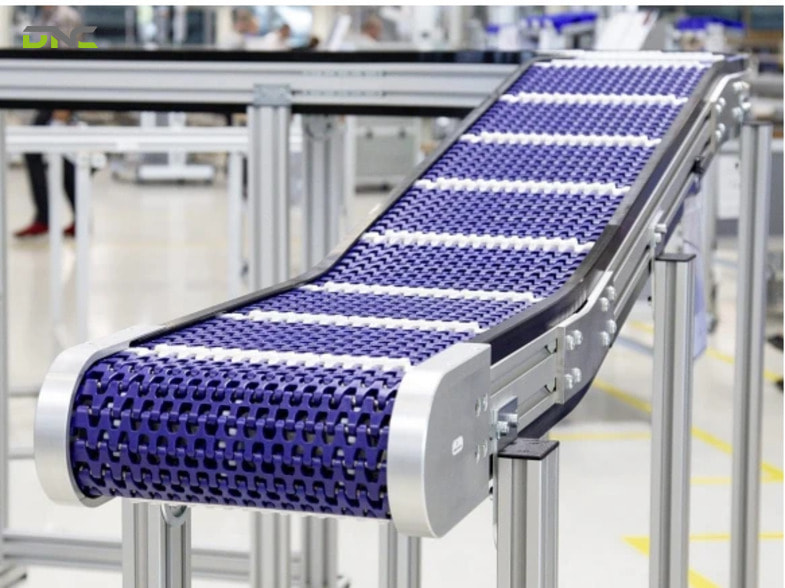
The belt design choices that follow the calculation are the belt type, the belt surface, the bed under the belt and the incline. One belt-system maker lists five parts of a conveyor belt system: the base frame, the return pulley, the glide plate, the flat or timing belt and the drive set.
Flat belts suit light to medium loads. A timing belt locks mechanically onto the drive pulley, so a narrower belt moves a heavier load.
The surface decides two things. An adherent surface copes with gradients, and the same maker carries workpieces on it at gradients of up to 20°, but it does not support accumulation. A non-adherent surface lets a smooth belt keep moving under stopped goods, which leaves time for a label or a camera inspection.
The surface choice also fixes the friction coefficient used in the tension step. The two decisions are one decision, so the coefficient must come from the belt that is actually specified. Tension then has to be held. For a flat-belt drive, one parts supplier names belt tension, the contact angle on the pulley and the friction coefficient as the key design parameters, and a wrongly adjusted tension makes the belt meander. The take-up must hold the T2 computed above, because a belt tensioned below it slips on the drive pulley.
Each of these belt conveyor choices ends up on paper, in the drawing that goes to fabrication.
Which Belt Design Choices Follow the Calculation?
What Goes on a Conveyor Belt Drawing?
A conveyor belt drawing shows the dimensions and positions that the calculation produced, so every result above lands on the drawing as a dimension or a note. The table below maps each result to the place where that result appears.
| Calculation result | Where it appears on the drawing | Example value from this article |
| Centre distance C | General arrangement dimension | 4.0 m (13.1 ft) |
| Pulley diameters D and d | Pulley schedule | 100 mm (3.9 in) |
| Belt length L and width | Belt schedule | 8.314 m (27.3 ft), 400 mm (15.7 in) |
| Belt speed and pulley rpm | Drive note | 0.5 m/s, 95.5 rpm |
| Motor power | Motor and gearmotor note | 0.10 kW at the belt before losses |
| T2 take-up tension | Take-up note | 244.7 N (55.0 lbf) |
| Incline angle | General arrangement view | 0° or 10° |
One bulk-conveyor manufacturer lists the drawings it supplies as belt, idlers, roller, pulley and structure drawings, so a full set is several sheets. Fabricators of general conveyors describe the step before fabrication in the same terms: a Malaysian fabricator names design and simulation, and another supplier names CAD and simulation packages used to visualise the system.
A drawing is an output of the calculation. A drawing without the calculation behind it carries dimensions that nothing has checked against load or power.
The conveyor drawing also carries the belt speed into the rest of the line, and on a packaging line that speed keeps working downstream.
How Does the Calculated Belt Speed Limit the Weighing Window of a Checkweigher?
The weighing window of a checkweigher is limited by the calculated belt speed: a pack rides fully on the platform, alone, for at most the gap divided by belt speed. For one pack to be alone on a platform of length Lp, the platform must be at least as long as the pack (length ℓ) and no longer than the pitch. The window is then (Lp − ℓ) ÷ v, and the maximum window is the gap ÷ v.
In the worked example, the gap is 200 mm (7.9 in) and the belt runs at 0.5 m/s, so the longest possible window is 0.4 s. At 120 packs per minute and the same pitch the belt runs at 1.0 m/s, and the window drops to 0.2 s. The window can never exceed the interval between packs, which is 1.0 s at 60 packs per minute.
An in-motion checkweigher reads each pack on the conveyor in fractions of a second, while a static load cell needs several seconds to stabilise, according to one weighing-equipment supplier’s FAQ. These window figures come from geometry alone, so they are DNC’s engineering inference and not a published specification. The real platform length and filter time are set by the checkweigher supplier.
None of the conveyor design pages crawled for this keyword mentions a checkweigher. Each lists speed as a free input. On a packaging line it is not free: throughput and pitch fix it, and it then limits the window.
DNC Automation integrates its checkweigher (JY / DNX-WR series) on a DNX-CV conveyor section, so the conveyor calculation and the weighing specification come from one engineering team. DNC recommends fixing the pitch, the gap and the platform length together, before the motor is quoted. Raising the packs per minute later shortens the window in inverse proportion.
With speed, tension, power and the weighing station fixed, the last question is how the calculation becomes a built conveyor.
How Does a Calculated Design Become a Built and Commissioned Line?
A calculated design becomes a built line through design review, fabrication, installation and commissioning, run by one accountable engineering team, which is what a turnkey conveyor project means. A Malaysian fabricator in Selangor describes the same chain: concept, design, simulation, fabrication, installation and commissioning from a single partner. A UK conveyor maker argues that a custom design fits the floor space, the product weight and dimensions and the processing speed, where a standard conveyor forces the process to fit the equipment. Industry rules enter at the same design review: the same maker ties food and beverage conveyors to HACCP-grade washdown design, pharmaceutical ones to GMP and stainless steel, hazardous areas to ATEX directives, and general machinery to CE marking.
DNC Automation designs, builds and integrates conveyors with PLC control, and the calculation above is the first step in that chain. The sequence is the same for heavy pallet loads: a pallet conveyor system starts from the load as its first input and works through the same six results.
The worked example is an illustration. A real specification replaces the assumed belt weight, the friction coefficient and the wrap factor with datasheet values for the belt and drive actually chosen. To check a conveyor calculation against your own production line data, speak with a DNC engineer.
What Do Engineers Ask About Conveyor Design Calculation?
Engineers ask five questions about conveyor design calculation more than any others, beginning with the formula for belt speed, and each answer below rests on the worked example and the published formulas in the sections above.
What is the formula for conveyor belt speed?
Belt speed is packs per minute multiplied by pack pitch, and pitch is pack length plus gap. At 60 packs per minute and a 500 mm (19.7 in) pitch, the belt runs at 30 m/min (98 ft/min). The pulley speed follows from the drive pulley diameter: π × D × rpm in plain geometry.
How do you calculate the power of a belt conveyor motor?
Belt conveyor power is effective tension multiplied by belt speed, where effective tension is the friction coefficient multiplied by the weight of belt and packs. The example gives 203.9 N × 0.5 m/s = 102.0 W (0.14 hp) at the belt, before gearbox and motor losses.
How do you calculate conveyor belt length?
Conveyor belt length is the pulley wrap plus twice the centre distance: L = (D + d)/2 × 3.1416 + 2C for pulleys of equal size. Two 100 mm (3.9 in) pulleys at 4.0 m (13.1 ft) centres need 8.314 m (27.3 ft) of belt.
What information does a manufacturer need to design a conveyor?
A manufacturer needs the conveyor length, width and height, the speed, the product weights, the controls and the application. A conveyor maker adds that food and pharmaceutical use must be stated up front, because food and pharmaceutical use changes the belt material and the frame.
What incline does a flat belt conveyor carry?
A flat belt conveyor with an adherent surface carries workpieces at gradients of up to 20° in one belt-system maker’s range, while a non-adherent surface supports accumulation and does not suit a slope. An incline also adds a lift term to the effective tension, as the 10° example shows.
- 2 views
- 0 Comment
Recent Comments