


Variable Frequency Drive for Pump: Sizing and Control
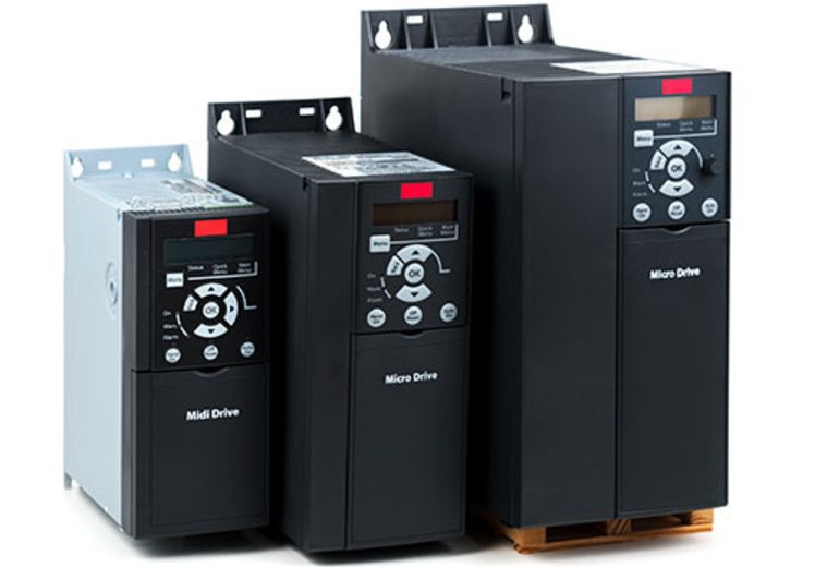
A variable frequency drive for pump duty, shortened to VFD, is a motor controller that changes the frequency and voltage supplied to a pump motor, so pump speed and flow follow the process. Power falls with the cube of speed, which makes a VFD the most direct way to cut pumping cost when flow varies. The saving stops where the static head begins: a pump still has to lift a fixed head, and that head sets a minimum speed. Six decisions shape a pump drive in Malaysian plants and HVAC loops: the affinity laws, the static and friction head split, pump type, control mode, drive sizing and the Siemens SINAMICS G120X range. They matter to engineers specifying centrifugal and positive displacement pumps on 50 Hz mains.
How a VFD Controls Pump Speed and Flow
A variable frequency drive controls pump speed by changing the frequency and voltage that reach the motor, and pump flow follows motor speed. Without a drive, a pump runs at one speed and one flow rate, and the only other state is off. With a VFD, the same pump covers a range of flow rates without a gearbox or a different motor.
Motor speed depends on supply frequency and pole count. On 50 Hz mains, a 4-pole motor turns at 1,500 rpm, and at 750 rpm when the drive outputs 25 Hz. Slip matters. Real induction motors run slightly below synchronous speed: a Hydraulic Institute article puts the slip at 1 % to 3 %, so a 4-pole motor on 60 Hz reaches 1,780 rpm at full load instead of 1,800 rpm.
The start changes too. A VFD applies a low frequency, 2 Hz or less, and ramps up along the volts-per-hertz curve. Direct-on-line starting draws an inrush of 500 % to 600 % of rated current, while the drive keeps peak start current near 150 % of full-load current, per the same Hydraulic Institute article.
Vendors label the device a frequency inverter, AC drive, inverter or VSD (variable speed drive). DNC Automation supplies and commissions the Siemens SINAMICS frequency inverter range for pumps, fans and compressors in Malaysian plants. Speed is only half of the picture, because the power a pump draws at that speed follows a stricter law.
Pump Affinity Laws: Flow, Head and Power at Part Speed
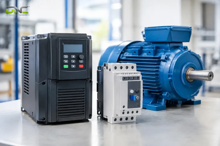
Under a variable frequency drive, the pump affinity laws state that flow varies with speed, head with the square of speed and power with the cube of speed. Wikipedia gives the best-known point: at 63 % speed a variable-torque pump or fan load consumes only 25 % of its full-speed power. For a 4-pole motor on 50 Hz mains, the table lists the arithmetic.
| Speed | Drive frequency | Flow | Head | Power |
| 100 % | 50 Hz | 100 % | 100 % | 100 % |
| 90 % | 45 Hz | 90 % | 81 % | 73 % |
| 80 % | 40 Hz | 80 % | 64 % | 51 % |
| 70 % | 35 Hz | 70 % | 49 % | 34 % |
| 63 % | 31.5 Hz | 63 % | 40 % | 25 % |
| 50 % | 25 Hz | 50 % | 25 % | 13 % |
At half speed, power is 13 %. The figures are derived from the cube law (0.8 x 0.8 x 0.8 = 0.512), not measured on a pump. Vendor quotes fit the same table. An HVAC contractor states a power saving of 87.5 % at half speed, which is 1 minus 0.125. A shaft-grounding vendor says a 25 % speed cut lowers energy use by about 60 %, and the cube gives 58 %.
Small speed cuts save little: a pump held at 95 % speed all day still draws 86 % of full power. The law rewards hours spent well below full flow. What the table cannot show is how much static head the real pipe adds to those power figures. How much of the cube a real system delivers depends on the pipe it works against, which is the next question.
Pump Affinity Laws: Flow, Head and Power at Part Speed
Static Head and Friction Head: Where the Cube Law Stops
A variable frequency drive saves energy only on the friction part of pump head, because static head and friction head are the two parts a pump supplies and the cube law governs only the friction part. Static head is the fixed lift or back pressure the pump works against at zero flow. Friction head is the loss in pipe, valves and fittings, and it grows with the square of flow.
A Hydraulic Institute article says VFDs are best applied in friction head-dominated pumping systems that undergo frequent load swings. The affinity laws explain why. Slowing a pump moves its whole head curve down by the square of the speed, but the static head stays where it is. Below the speed at which the pump’s head at zero flow drops under the static head, the pump delivers nothing. A static-head-dominated system has a minimum useful speed, and its operating points no longer sit on one cube-law curve, so power falls more slowly than the cube of flow.
The table sets the two pump system types side by side. The duty examples are an engineering reading of the sources, not measured data.
| Attribute | Friction-dominated system | Static-head-dominated system |
| Head at design flow | Mostly pipe, valve and fitting losses | Mostly elevation lift or fixed back pressure |
| Head at zero flow | Near zero | Near the static head |
| Power at part flow | Follows the cube law closely | Falls more slowly than the cube law |
| Minimum useful speed | Low | High, set by the static head |
| Typical duty | Closed circulating loops, long process lines | Pumps lifting liquid to a tank or upper floor |
A drive-maker page describes the matching control logic: a pressure sensor near the discharge gives a reference, and the drive keeps adjusting that reference to follow the system curve.
The three questions below are the ones that settle whether a drive earns its place on a given pump:
- What share of the design head is static?
- How many hours a year does the pump run below full flow?
- Does the process need constant flow or constant pressure?
DNC recommends answering the first question before any drive is quoted. The second question leads to the alternatives for setting flow.
VFD vs Throttling Valve vs Fixed Speed
A variable frequency drive sets pump flow by changing motor speed, a throttling valve sets it by adding restriction, and a fixed-speed pump has one flow rate. The table compares the three ways to run a pump below its full flow.
| What matters | Fixed speed | Throttling valve | VFD |
| How flow is set | One speed, one flow; the only other option is off | Valve adds restriction downstream | Drive changes motor speed and flow follows |
| Power at lower flow | Full draw while running | Stays high; the pump still works against the valve | Falls faster than speed |
| Start-up | Direct-on-line inrush of 500 % to 600 % of rated current | Same as fixed speed | Low-frequency start, peak near 150 % of full-load current |
| Extra hardware | A standard motor | The valve plus sensors | A VFD and a motor that handles drive duty |
A pump maker adds that a drive eliminates or reduces the number of control valves, each of which needs its own sensor installed and maintained. Isolation valves usually stay for servicing the line. The drive, not the valve, sets flow. A throttled pump wastes power twice: the motor keeps full speed, and the valve turns the surplus into heat. The saving from a drive depends on how often the pump runs below full flow, so the numbers change from site to site.
Controlled ramps carry one more benefit that fixed speed lacks. The Hydraulic Institute notes that controlled acceleration and deceleration limit hydraulic transients, and that levelling out pressure spikes protects piping from rupture. The pump type decides how well the drive handles the start, which brings in torque.
Centrifugal vs Positive Displacement Pumps on a VFD
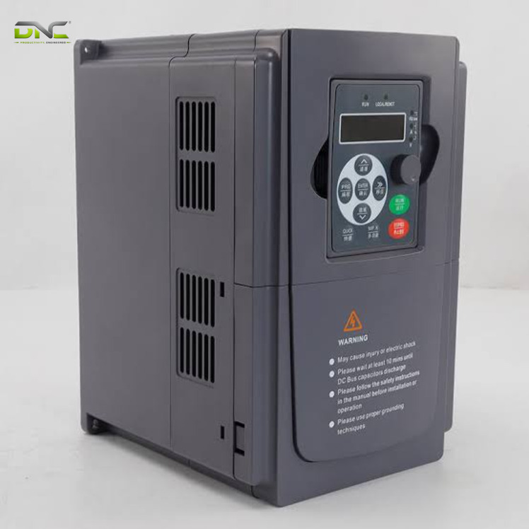
A variable frequency drive sees centrifugal pumps as variable-torque loads and positive displacement pumps as constant-torque loads, and the difference sets the drive rating. Rotodynamic pumps have reduced torque at reduced speed. Positive displacement pumps, which include reciprocating piston, plunger and diaphragm designs and rotary gear and screw designs, can deliver full pressure at reduced speed. Because that torque stays high at low speed, motor cooling becomes a greater consideration.
| Attribute | Centrifugal (rotodynamic) | Positive displacement |
| Torque at reduced speed | Falls with speed | Stays at full-pressure level |
| Starting with a VFD | Lower start demand | Higher start demand; flow may need bypassing until the motor reaches speed |
| Drive overload rating | Variable torque: 110 % to 120 % of rated amps for one minute | Constant torque: 150 % for one minute |
| Motor cooling at low speed | Usually not an issue | A greater consideration |
The overload figures come from a drive distributor. Manufacturers label overload with terms such as light duty, normal duty and heavy duty, and those labels are not standardised. Compare the overload percentage over 60 seconds instead of the label.
The cube law applies to variable-torque loads. A constant-torque load draws power in proportion to speed, so the case for a drive on a positive displacement pump rests on process control and soft starting more than on energy. DNC recommends specifying the drive against the pump’s torque curve first and its nameplate kilowatts second. Torque first, kilowatts second. What the drive reads in order to set that speed defines the control mode.
Centrifugal vs Positive Displacement Pumps on a VFD
Pump Control Modes: Constant Pressure, Flow and Level
A variable frequency drive sets the pump control mode through its feedback sensor: constant pressure, constant flow or constant level. Automatic systems use feedback from flow, level and pressure sensors to regulate the frequency output, while small installations use a dial potentiometer, pushbutton or keypad.
| Mode | Feedback sensor | What the drive holds |
| Constant pressure | Pressure sensor near the discharge | Discharge pressure, by following the system curve |
| Constant flow | Flow sensor in the line | Flow rate, by trimming speed |
| Constant level | Level sensor in the tank or sump | Level, by raising or lowering speed |
| Manual | Potentiometer, pushbutton or keypad | A set speed |
So sensor placement matters: near the discharge, a pressure sensor gives the drive the reference it follows. Most drives also take a speed reference from hardwired or networked signals. A keypad can be mounted remotely, and most drives have input and output terminals for pushbuttons, switches and control signals.
Ramp settings protect the pump as much as the mode does. The volts-per-hertz curve should match the torque load: too high a voltage at a given frequency wastes energy and can overheat the motor, and too low a ratio may not develop enough torque. On stopping, a ramp set too fast makes the motor regenerate and raises the DC bus voltage, which can damage the drive. Controlled ramps in both directions also keep pressure transients in the pipe low. Settings only help while the pump has liquid to move, so protection against dry running comes next.
Pump Protection: Dry Run, No Flow and Drive Faults
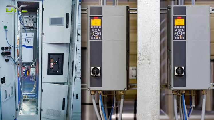
Pump protection in a variable frequency drive covers the pump, the motor and the drive, and the drive reports current, voltage, motor temperature, speed and torque for diagnosis. Drive makers build pump-specific functions into the firmware. Dry Pump Protection and End of Curve act when the pump runs without creating the desired pressure, for example when a pipe leaks. The No/low flow function detects a pump that runs fast but is not fully loaded, which points to stopped circulation, a dry pump or a leak.
The reaction is programmable: the drive raises an alarm, shuts off the pump or performs another pre-programmed action. A drive maker also lists overload prevention by reducing speed, so supply continues at lower flow.
Which side raised the alarm? Some faults come from the drive side. The table maps common drive faults to the pump condition behind them, as listed by a pump maker.
| Drive fault | Typical pump-side cause |
| Overcurrent | Start-up, blockage or overload |
| Overvoltage | Pump inertia during deceleration pushing energy back into the drive |
| Undervoltage | Unstable supply, slowing the pump |
| Overheating | Dust, wet or poor ventilation, or an undersized drive |
| Phase loss | Unbalanced supply or wiring, then vibration and motor damage |
| Motor overload | Higher system resistance or debris |
A drive also helps with a test. Lowering the speed gradually shows cavitation if performance improves as speed drops, and ramping the speed up and down shows the speeds where vibration rises. The drive cannot find a blockage, a worn impeller or a leak by itself. It only narrows the search. Once these protections are set, the remaining task is to put the checks into one decision.
Pump Protection: Dry Run, No Flow and Drive Faults
Summary: Four Checks Before a VFD Goes on a Pump
Four checks decide whether a variable frequency drive earns its place on a pump: flow variation, head split, pump type and sensor. A pump drive pays back when flow varies, when friction carries most of the head and when the drive matches the pump’s torque and sensor. A throttling valve and fixed speed keep full power at lower flow, and static head sets a minimum speed. The pump type sets the overload class, and the feedback sensor sets the control mode. The table gives the four checks in order, with the result that favours a drive.
| Check | Question | Where it is decided | Result that favours a drive |
| 1 | Does flow vary, and for how many hours a year? | Duty profile | Many hours below full flow |
| 2 | Is the head mostly friction or mostly static? | System curve | High friction share, low static share |
| 3 | Is the pump centrifugal or positive displacement? | Overload class | Either, with the matching 110 % to 120 % or 150 % rating |
| 4 | Which sensor sets the speed: pressure, flow or level? | Control mode | A sensor and a setpoint exist |
One failed check does not end the case. A positive displacement pump on a static-head system saves little energy, yet it may still need a drive for process control and soft starting. A fifth point, the drive and motor rating, decides whether the four checks survive installation.
Sizing a VFD for a Pump: Overload, Motor and Cable
Sizing a variable frequency drive for a pump starts from the overload the pump needs and ends with the motor, the cable and the enclosure around the drive. The overload class from the pump type fixes the current rating. A drive distributor sizes against the overload of the motor and the driven equipment, which is why a positive displacement pump needs a heavier-rated drive than a centrifugal pump of the same power.
The motor needs checking next. The drive switches at high frequency, and the spikes reach the winding insulation. A pump maker says standard NEMA motors are usually fine at 230 V and that a motor built for inverter duty is the choice at 460 V; motors for inverter-fed duty follow Part 31 of NEMA MG-1. Check your motor datasheet against your supply voltage. Close-coupled single-stage pumps tend to see less resonance than framed or multistage units, and a pump-motor set that runs across a speed range can excite natural frequencies, so ask the manufacturer for the excitation frequencies in the operating range.
Bearing damage is the second motor risk. The drive creates common-mode voltage that builds a shaft voltage, and the discharge can pass through the bearings. A shaft-grounding vendor calls electrical bearing damage likely the most common cause of failure in motors on drives today. The Hydraulic Institute article recommends a shaft grounding system plus electrical isolation of the shaft and bearing.
Cable length matters most on submersible and down-well pumps. A long lead between drive and motor produces a reflected wave that shortens motor life. Reference sources put the threshold at 30 to 50 m (100 to 150 ft), and a drive distributor adds that cables over a couple of hundred feet need output filters such as load reactors, dV/dt filters or sine-wave filters. In a submersible or down-well installation, the motor can sit at the top of the well while the pump sits at the bottom. The cable that counts is the one between drive and motor, not the one down the well.
The enclosure closes the sizing list. Heat is one of the biggest killers of drives, so a drive belongs in an electrical room or behind cooling fans. Splashing, humidity and chemicals call for a sealed enclosure, and the distributor quotes NEMA 4, 4X and 3R classes. NEMA classes are US designations, so agree the equivalent IP rating with the panel builder.
Each pump on a drive also needs a feeder. An MCC panel is a shared power bus with one starter feeder per motor, and the starter type follows from each motor. DNC Automation lists VFD and soft starter panels and MCC and motor control within its electrical and instrumentation service. Both pages carry no panel specification, so request panel details from DNC directly. Sizing settles the drive for one pump, and the same logic carries into buildings.
VFD in HVAC: Chilled Water and Booster Pump Loops
A variable frequency drive in HVAC drives the motors of chilled water pumps, booster pumps, fans and compressors, and the pump rules above apply unchanged. HVAC systems are designed for peak load and rarely run there. At part flow, which is where the cube law pays, a pump spends most of its hours. An HVAC contractor lists chilled water systems in primary-secondary and variable primary arrangements, where drives balance water flow.
The head split from earlier explains the difference between loops. A closed chilled water loop adds no net lift, so its head is mostly friction and it follows the cube law closely, which is an engineering reading of the sources. A booster pump that serves the upper floors of a tall building carries a static share. A vendor blog says that a conventional booster cannot hold pressure precisely, while a drive holds pressure at every level and lowers energy use.
Savings claims in this field are vendor figures. One blog states that drive-equipped HVAC motors often use 50 % or less of the energy of direct-on-line motors and that the payback is generally under three years. Treat both as ranges to test against your own running hours. The same blog repeats the bearing warning: HVAC motors on drives need shaft grounding.
Drive makers also build HVAC functions for pumps. A refrigeration and air-conditioning drive keeps the water or glycol supply running during a leak or broken pipe by reducing speed. Fans on air handling units and cooling towers obey the same affinity law, but they need their own page. DNC’s drive range answers the pump side of HVAC, and the range is the next topic.
VFD in HVAC: Chilled Water and Booster Pump Loops
Siemens SINAMICS Drives for Pumps in Malaysian Plants
Siemens SINAMICS frequency inverter families from DNC Automation come in four series, and SINAMICS G120X is the one built for pumps. The table gives each series with its power range as published on the DNC frequency inverter page.
| Series | Power range | Position |
| SINAMICS V20 | 0.12 to 30 kW (0.16 to 40 hp), 7 frame sizes | Compact drive with quick commissioning |
| SINAMICS G120C | 0.55 to 132 kW (0.75 to 150 hp), 7 frame sizes | Compact vector drive |
| SINAMICS G120 | 0.37 to 250 kW (0.5 to 400 hp), 200, 400 and 690 V variants | Modular vector drive with Safe Torque Off, Safe Stop 1, Safety Limited Speed and Safe Brake Control |
| SINAMICS G120X | 0.75 to 630 kW (1 to 700 hp) | Infrastructure pump, fan and compressor drive for water and wastewater, HVAC, irrigation and industrial chiller and refrigeration |
The smallest pump drive ratings are 0.12 kW (120 W / 0.16 hp) on V20, 0.55 kW (550 W / 0.75 hp) on G120C and 0.75 kW (750 W / 1 hp) on G120X.
The G120X range spans 0.75 to 630 kW in one drive family, so one family covers small and large pump duties. DNC recommends matching the series to the pump duty after the four checks in the summary, and listing the pump duty, the motor, the cable run and the feedback sensor in one specification, because each check depends on them. Four pump VFD questions recur once a drive is in service, and the FAQ answers them in turn.
Frequently Asked Questions About Pump VFDs
Frequently asked questions about a variable frequency drive for pump duty follow from the four checks above, and each answer applies the same rule. The first answer concerns the case in which a drive adds nothing.
When does a pump need a VFD?
A pump needs a VFD only when its flow varies, because the saving depends on how many hours the pump runs below full flow. A pump that runs at one flow all day gains nothing from the cube law. A pump on a static-head-dominated system gains less than one on a friction-dominated system.
Can a VFD run a three-phase pump motor from a single-phase supply?
Some VFDs run a three-phase motor from single-phase input, because the drive converts the input to DC and rebuilds three-phase output. The drive acts as phase converter and speed controller. A drive on single-phase input must be de-rated, as the Hydraulic Institute article states.
What happens to the control valve when a VFD goes on a pump?
The control valve mostly disappears, and sometimes disappears entirely, because pump speed replaces restriction as the way to set flow. Isolation valves usually stay so the line can be serviced.
Can a pump run faster than its rated speed on a VFD?
Running a pump above rated speed needs approval from the pump and motor manufacturer. The drive itself outputs frequencies above 50 Hz. Power rises with the cube of speed, so a 10 % overspeed asks for 33 % more power (1.1 x 1.1 x 1.1 = 1.331).
- 0 views
- 0 Comment
Recent Comments