


Industrial Robot End Effector: Types, Grip Force, Selection

An industrial robot end effector is the tool on the wrist flange of a robot arm that grips, processes or senses the workpiece, so it fixes the operations a robot cell performs. The arm moves the tool. The end effector does the work. Four classes (grippers, process tools, sensors and tool changers) and four grip principles (impactive, ingressive, astrictive and contigutive) organise the family.
Grip force, payload at the flange, an ISO 9409-1 interface, an IEC 60529 enclosure rating and ISO 10218 requirements limit the choice. DNC Automation fits end effectors to Comau and Doosan robot arms in palletizing and end-of-line cells for Malaysian manufacturers. Four classes, four principles, one grip-force formula and six specification inputs follow for plant engineers.
An industrial robot end effector is the tool at the flange that decides what a robot arm can do
An industrial robot end effector is the device at the end of the robot arm that interacts with the workpiece, typically a gripper or a tool. In the strict sense it is the last link of a serial manipulator, and the tool bolts onto that link. Wheels on a mobile robot and feet on a humanoid are not end effectors, because they move the robot instead of acting on the work.
A robot arm without a tool performs no operation. It reaches a point in its workspace and stops there. The arm supplies position, and the end effector supplies the action.
The words around the tool overlap, so the vocabulary needs fixing. End-of-arm tooling (EOAT) is the industry term for the same device. A gripper is one class of end effector, the class that grasps and releases parts. A manipulator is the arm itself, and an actuator is the joint motor that moves it. Phrases such as gripper robot arm and robot arm gripper describe an arm fitted with a gripper, one choice among four classes.
DNC Automation specifies the end effector as part of the turnkey cell, not as an accessory ordered after the arm. Industrial robotic solutions differ in arm size and controller, yet the tool decides the result. DNC’s industrial robotic solutions for Malaysian manufacturers start from the part the tool must hold or work on, and the arm, controller and guarding design follow from that part. Which of four end effector classes the task calls for is the first selection decision.
Four end effector classes cover grippers, process tools, sensors and tool changers
Four robot end effector classes cover grippers, process tools, sensors and tool changers, and the task decides which class the cell uses. Pick-and-place, assembly, machine tending and palletizing call for a gripper. Welding, painting, deburring and sanding call for a process tool. Inspection calls for a sensor. A cell that changes task during a shift calls for a tool changer.
Guides disagree on one boundary. A force-control manufacturer places the tool changer between the wrist and the end effector and excludes it from the class. A robot-cell integrator lists the tool changer among seven end effector groups. Both agree that the changer carries the tool, so the tool changer is counted here as the fourth class.
The table below sets the four end effector classes side by side by what each one does to the workpiece.
| Class | What it does to the workpiece | Examples | Where it sits |
| Gripper | Holds and releases it, leaves it unchanged | Parallel jaw, vacuum cup, magnetic gripper | At the tool flange |
| Process tool | Changes it | Welding torch, spray nozzle, sander, electric screwdriver | At the tool flange |
| Sensor | Measures it | Vision sensor, laser scanner, proximity sensor, force-torque sensor | At the tool flange or inside the gripper |
| Tool changer | Swaps the tool that acts on it | Master plate and tool-side holder with electrical and I/O pass-through | Between wrist and tool |
A sensor end effector turns the robot arm into a programmable sensor-orientation device, which suits inspection with less hands-on time. Vision sensors report where to move, what to pick and how the object lies. A fixed vision inspection system moves the part past the camera. An arm-mounted sensor moves the camera past the part.
Grippers form the largest of the four classes, and they divide further by the physical effect that holds the part.
Robot arm grippers, the largest end effector class, hold parts through four principles
Robot arm grippers hold parts through four physical principles: impactive, ingressive, astrictive and contigutive, according to the reference classification of robotic prehension. Impactive grippers close jaws or claws that grasp by direct impact. Ingressive grippers push pins, needles or hackles into the surface, as in textile, carbon fibre and glass fibre handling. Astrictive grippers apply attractive forces to the surface by suction, magnetism or electroadhesion. Contigutive grippers need direct contact for adhesion, through glue, surface tension or freezing, and they are the least used at macro scale.
Two groups of end effector grippers cover most of what a Malaysian production line buys: impactive jaws and astrictive pads.
Impactive end effector jaws: parallel, three-jaw and adaptive grippers
Impactive robot end effector jaws hold a part by direct impact, and parallel, three-jaw and adaptive grippers are the three common forms. A parallel gripper moves two jaws in step along parallel tracks and grips from opposite sides. It is fast, strong and limited to parts with two parallel faces. A rotary variant adds a 90° or 180° turn, so the gripper picks in one orientation and places in another.
A three-jaw radial gripper closes three jaws equally toward the centre, like a drill chuck. It holds cylinders and spheres on their axis and delivers a lower grip force than a parallel gripper of equal size. Adaptive grippers wrap soft or articulated fingers round irregular or delicate items such as food. They run slower and cost more. Fingered grippers come with two to five fingers, and six or more are rarely needed. A wide gripper trades force for stroke, so large cartons and appliances fit while force per unit of size falls.
Power arrives as electricity, compressed air or hydraulic fluid. A servo-electric gripper takes force, position and speed commands and reports part-picked status to the controller. A pneumatic gripper is fast and light and depends on an air supply in the cell. Impactive jaws close on the part, and the next group holds it from one side only.

What are the three types of robotic systems?
Astrictive and ingressive end effectors: vacuum, magnetic, Bernoulli and needle grippers
Astrictive and ingressive robot end effectors hold a part without closing jaws around it. A vacuum gripper sucks the part onto a pad, which suits glass, cardboard, plastic and thin sheet metal when the surface is dense enough to seal. Vacuum grippers move sealed or taped cases in robotic palletizing, and they do not suit crates or open boxes. A magnetic gripper holds ferromagnetic parts only.
A Bernoulli gripper lifts a part on an airflow cushion without touching it, which is why wafer and photovoltaic cell handling uses it. A needle gripper pierces the surface of textiles and fibre mats. Vacuum cups and electromagnets dominate automotive and sheet-metal handling.
The table below maps each gripper type to its principle, its parts and its limit.
| Gripper type | Principle | Fits | Limit |
| Parallel jaw | Impactive | Rigid parts with two opposite parallel faces | Needs access to both faces |
| Three-jaw radial | Impactive | Cylindrical and spherical parts | Lower force than an equal parallel gripper |
| Adaptive multi-finger | Impactive | Irregular, delicate and food items | Slower and costlier |
| Wide jaw | Impactive | Large cartons, appliances, panels | Lower force per unit of size |
| Vacuum | Astrictive | Smooth, dense surfaces: glass, cardboard, plastic | Fails on crates, open boxes and surfaces too open to seal |
| Magnetic | Astrictive | Ferromagnetic metal parts | No other materials |
| Bernoulli | Astrictive, contactless | Wafers, photovoltaic cells, textile, leather | Light, thin parts |
| Needle | Ingressive | Textiles, carbon and glass fibre | Penetrates the surface |
Every row of that table also decides where the end effector leaves the part inside the hand, and that position sets the next problem.
An end effector centres, carries or absorbs the part’s position error
A robot end effector centres, carries or absorbs the position error of the part it picks, depending on its grip principle. Position error is the distance between where the part lies and where the program assumes it lies at the moment of the grip. Arm datasheets quote repeatability in millimetres. The tool decides how much of the part’s offset is added to that figure at the place point.
Jaws centre. Synchronous parallel jaws pull both faces to the jaw midline, so the part leaves the pick centred along the jaw axis. A radial three-jaw gripper centres in two directions, which is why cylinders sit on the axis of the hand. Both remove the error they reach.
Pads carry. A vacuum plate or a magnet end effector grips the part where it lands. The pad has no datum to push the part toward, so an offset at the pick becomes an offset in the hand and then an offset at the place. This is DNC’s engineering reasoning from the mechanics of each principle.
Compliance absorbs. A compliant tool gives way where the part is misaligned. Machine loading is the example: the tool needs freedom in two axes so misaligned pieces are not crushed, and no freedom in the loading direction.
The table below states what the place point inherits from each end effector behaviour.
| Behaviour | Gripper types | What the place point inherits |
| Centres | Parallel jaws, three-jaw radial | Offset along the jaw axis removed, offset across it unchanged |
| Carries | Vacuum plate, magnetic gripper | The full pick offset plus arm repeatability |
| Absorbs | Passive or active compliant tools | Offset taken up by the tool, force limited |
Take a palletizing cell as an illustration. A carton carried at a 6 mm (0.24 in) offset on a vacuum plate end effector reaches the pallet 6 mm off its pattern coordinate before arm repeatability adds its own error. The 6 mm is an assumed value, and the logic holds for any value.
When the upstream conveyor presents parts with scatter wider than the downstream tolerance, a centring grip, a locating station or a vision-guided pick removes the scatter. A suction grip alone does not. Specifying the tool therefore starts with two tolerances, one at the pick and one at the place.
Four end effector classes, four principles and this tolerance question summarise the choices made so far.
Summary: four classes, four principles and one tolerance question fix the end effector
Four robot end effector classes, four grip principles and one tolerance question fix the end effector before any force is calculated. The classes are grippers, process tools, sensors and tool changers. The principles are impactive, ingressive, astrictive and contigutive. The class answers what the tool does to the part, the principle answers how it holds the part, and the tolerance answers where the part ends up.
The tolerance question asks whether the pick scatter must be centred, carried or absorbed to meet the tolerance at the place. A parallel or three-jaw gripper centres. A vacuum or magnetic pad carries the offset. A compliant tool absorbs it. The force figure comes next.
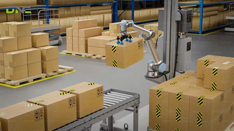
image1
End effector grip force follows from mass, acceleration, friction and finger count
Robot end effector grip force follows from four inputs: part mass, acceleration, the friction coefficient between pad and part, and the number of fingers. Friction carries the part in a jaw grip. The normal force that the jaws apply must therefore produce friction larger than the weight plus the acceleration load.
The standard form for an end effector is F = m (a + g) / (μ n), where F is the normal force per finger in newtons, m is the part mass in kilograms, a is the acceleration of the move in metres per second squared, g is gravity at 9.81 m/s² (32.2 ft/s²), μ is the friction coefficient and n is the number of fingers. A move upward against gravity needs more force than a move downward, which the (a + g) term captures.
The table below works four end effector cases for a 2 kg (4.41 lb) part. All four cases use assumed values chosen to show the arithmetic.
| Case | Acceleration | Friction μ | Fingers | Force per finger |
| Reference | 5 m/s² (16.4 ft/s²) | 0.30 | 2 | 49.4 N (11.1 lbf / 5.0 kgf) |
| Slippery pad | 5 m/s² (16.4 ft/s²) | 0.15 | 2 | 98.7 N (22.2 lbf / 10.1 kgf) |
| Three fingers | 5 m/s² (16.4 ft/s²) | 0.30 | 3 | 32.9 N (7.4 lbf / 3.4 kgf) |
| Faster move | 10 m/s² (32.8 ft/s²) | 0.30 | 2 | 66.0 N (14.8 lbf / 6.7 kgf) |
Friction dominates the end effector result. Halving μ doubles the force. Doubling the acceleration raises it by a third. A third finger cuts the load per finger by a third.
A cell designer applies a safety margin on top of the result and never sizes the gripper to its limit. For a vacuum gripper the usable suction area is the key figure, and for a mechanical gripper the shape of the jaws is. The same arithmetic runs on the real part mass, the real move profile and the measured friction of the pad.
Force sets the size of the tool, and the size of the tool sets the mass the arm must carry.
The end effector spends payload and cycle time before the product does
The robot end effector spends part of the arm’s rated payload and cycle time before the product does. The payload rating has to carry the workpiece and the end effector together. A heavy gripper reduces the payload left for the product.
Take a 10 kg (22.0 lb) carton and a 2.5 kg (5.5 lb) gripper. The arm carries 12.5 kg (27.6 lb) at the flange. One global robot maker lists its small robots up to 12 kg (26.5 lb), so the sum moves the cell into the next class. The product alone fits the small class. The product plus the tool does not.
Cycle time follows mass. A lightweight gripper accelerates faster and shortens the cycle, which decides throughput in high-volume production. A stronger grip asks for a larger tool, a larger tool weighs more, and a heavier tool slows the move. The designer balances three figures that pull against one another: grip force, tool mass and cycle time.
In an end-of-line cell, the heaviest carton the checkweigher accepts, plus the tool, is the payload case. The tool is sized for the heaviest and the most delicate variant the cell handles, not for the sample part that passed the trial.
Mass is one interface between tool and arm. The flange, the utilities and the enclosure are the others.
End effector flange, enclosure and safety follow named standards
The robot end effector flange, enclosure and safety follow three named standards: ISO 9409-1, IEC 60529 and ISO 10218. ISO 9409-1 specifies the flange dimensions, so a tool and an arm that both follow it bolt together. Utilities travel through the same interface: electrical power, compressed air or a bus signal. One robot-component distributor lists tool-free mechanical coupling, repeatable positioning and electrical and I/O pass-through as the features of a tool changer.
IEC 60529 defines the IP code, which rates how well the tool is protected against dust and water. A cell in the food industry demands a higher rating than a dry assembly line. In the IP code a first digit of 5 means limited dust ingress and 6 means dust-tight.
ISO 10218-1 and ISO 10218-2 cover industrial robots, and ISO/TS 15066 adds the technical specification for collaborative applications. The risk assessment covers the entire cell, and the tool is part of it. On a collaborative robot the end effector carries no sharp edges or pinch points. Collaborative grippers trade grip force for low mass, pinch-free shapes and force limiting, and the same trade appears in the comparison of cobot vs industrial robot palletizers.
Robot makers list certified end effectors in partner programmes, and a certified plug-in shortens the programming step. Commissioning a tool follows four steps: mount it on the wrist, connect power, connect communications to the controller, and add the tool to the robot program.
Everything so far assumes the tool holds the part. A process tool changes it instead.

An end effector that changes the workpiece uses process tools and compliance devices
A robot process tool changes the workpiece, and a compliance device keeps that tool in contact at a set force. Welding torches, spray nozzles, machining heads, sanders, grinders, deburring tools and electric screwdrivers are process tools. A gripper only grasps the part. A process tool alters it.
Compliance comes in two forms. Passive compliance is an open-loop device, usually set by a customer-supplied air pressure regulator, and it suits flat or prismatic parts where high-accuracy force control is unnecessary. Active compliance is a closed loop that uses force, acceleration and position sensors to apply the set force over complex contours in any orientation. A tool with gravity compensation balances its own weight in any orientation, so the defined force holds without extra programming.
Surface finishing shows why this matters. A stiff sanding tool presses too hard or lifts off where the surface varies, and the part is damaged or finished unevenly from one piece to the next. A compliant tool evens out the irregularities.
A second decision sits beside the tool choice. The robot either carries the tool to the part (tool-to-part), or the gripper carries the part to a fixed grinder (part-to-tool).
Tool-to-part needs a custom end effector for the job. Part-to-tool frees the arm for another task and needs no custom end effector. Neither is wrong. The pieces needed in a given time and the finish quality decide.
Whichever route the cell takes, the end effector specification request lists the same inputs.
Six inputs complete an end effector specification
Six inputs complete a robot end effector specification request: part, position tolerance, cycle, arm, environment and utilities. The six inputs below let an engineer size the tool without a second round of questions.
- Part: mass, dimensions, material, surface condition and the heaviest and most delicate variant.
- Position tolerance: the scatter of the part at the pick and the tolerance required at the place.
- Cycle: picks per minute and the acceleration of the move profile.
- Arm: make, model, rated payload and flange standard.
- Environment: dust, washdown, temperature, hygiene rules and the IP rating required under IEC 60529.
- Utilities: electrical supply, compressed air and the bus or I/O signal available at the flange.
Specification requests repeat the same misses. The mass of the tool is left out of the payload sum. The tool is designed for the clean sample part and meets tolerances and problem cases in production. The cycle time is checked late, after a heavy tool has slowed the move.
The flange or a utility does not match the arm. The position tolerance at the place is the fifth miss, and it decides whether the tool must centre the part.
Malaysian plants automating under the Industry 4.0 push of the New Industrial Master Plan 2030 (NIMP 2030) put these six inputs into the quotation request. To have DNC check the six end effector inputs against your production line, talk to our engineers about the cell.
Five short answers follow on the end effector specification points above.
Six inputs complete an end effector specification
Frequently Asked Questions
Frequently asked questions about the industrial robot end effector receive five answers below, which cover the definition, the gripper link, selection, grip force and tool changers in plant specifications.
What is an industrial robot end effector?
An industrial robot end effector is the tool at the end of the robot arm that grips, processes or senses the workpiece. It is also called end-of-arm tooling (EOAT). Grippers, welding torches, sanders and cameras are all end effectors. The robot handles the movement, and the end effector handles the task.
Is a gripper the same as an end effector?
No, a gripper is one class of end effector. The gripper grasps and releases parts, while the broader term also covers process tools, sensors and tool changers. In everyday use the two words often mean the same device, because grippers are the most common end effector in pick-and-place, assembly and palletizing.
How do you choose an end effector for a robot arm?
Choose the end effector for a robot arm by the grip principle the part needs first, then size force, payload and flange. The order is workpiece, task, environment, robot type and cycle time. Smooth dense surfaces call for vacuum, solid contours for jaws and ferromagnetic parts for magnets. The tolerance at the place then decides whether the tool must centre the part.
How much grip force does a robot arm gripper need?
A robot arm gripper needs the force that F = m (a + g) / (μ n) returns, plus a safety margin. For an assumed 2 kg part moved at 5 m/s² with a friction coefficient of 0.30 and two fingers, each finger applies 49.4 N (11.1 lbf). A lower friction coefficient raises the force in proportion.
What does a tool changer do for a robot end effector?
A tool changer lets the robot swap end effectors automatically between grippers, screwdrivers, suction cups and welding torches. It has a robot-side master and a tool-side holder, with tool-free coupling and electrical and I/O pass-through. A cell that runs several tasks or frequent changeovers uses one to avoid manual rework.
- 1 views
- 0 Comment
Recent Comments