


What Is a PLC? Types, Wiring Diagram and Advantages
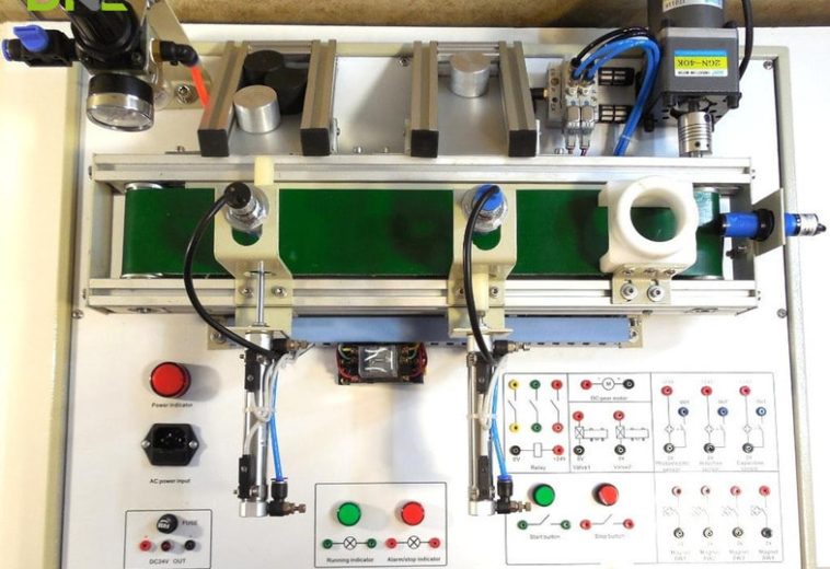
A PLC (programmable logic controller) is a ruggedized industrial computer that reads sensor inputs, runs a stored program and switches motors, valves and contactors through its outputs. The first PLC, the Modicon 084, was built in 1969 in answer to a General Motors request to replace hard-wired relay panels, and the same read-execute-write loop still runs conveyors, palletizers and checkweighers.
Four decisions define an installation: how the PLC is wired, which type it is, what it gains over relay panels and which layers sit above it. The terminal strip links the first two, because the type fixes how many terminals exist and which loads they switch. DNC Automation specifies Siemens SIMATIC controllers for packaging, weighing and conveyor lines in Malaysia.
PLC Definition and Origin
The PLC definition is short: a programmable logic controller is a ruggedized industrial computer that reads inputs, executes a stored program and updates outputs in a repeating loop. Input devices such as pushbuttons, limit switches and proximity sensors feed the PLC. Output devices such as contactor coils, solenoid valves and drive references carry its decisions back to the machine.
A PLC tolerates the heat, vibration, electrical noise, dust and humidity that stop an office computer, per one platform vendor. What separates it from a desktop PC is deterministic execution, not computing power: the program runs in the same order and in a predictable time on every scan, whereas a general-purpose operating system can pause logic for 200 milliseconds (0.2 s / 200,000 microseconds), according to the same vendor.
Before the PLC, control logic lived in relays, cam timers and drum sequencers, and every change meant rewiring. In 1968 the Hydramatic division of General Motors issued a request for proposals for an electronic replacement of hard-wired relay systems. Bedford Associates won it, and the unit built in 1969 was designated 084 because it was the firm’s eighty-fourth project, according to Wikipedia. Its maker, Modicon, took its name from “modular digital controller”, and Dick Morley, who worked on the project, is considered the father of the PLC.
That 1969 unit repeated one loop for as long as it was powered, and what is PLC hardware today still comes down to the same loop.
PLC Scan Cycle and Main Components
A PLC scan cycle is the loop of reading inputs, executing the program and writing outputs that the controller repeats for as long as it is powered. Wikipedia gives three steps, and most vendors add a fourth.
The input scan copies the state of every PLC input into memory as one snapshot. Program execution runs the logic from the first instruction to the last against that snapshot. The output update writes every result to the output modules together. Housekeeping then handles communications and self-diagnostics before the next scan starts. Nothing updates mid-scan.
One PLC scan takes tens of milliseconds, and one platform vendor gives 1 to 50 milliseconds (0.001 to 0.05 seconds, or 1,000 down to 20 scans per second) depending on program size and controller model. A 10 ms scan (0.01 s / 100 scans per second) makes 100 complete decisions every second. Scan time sets a hard design limit.
The snapshot has a price. Because the PLC works on one snapshot, a signal shorter than one scan can be missed. Pulse counting from a shaft encoder and precise timing move to dedicated counter or timing modules for that reason, per Wikipedia.
A PLC has seven functional parts, and the table lists what each part does.
| Part | What it does |
| Power supply | Converts plant power into stable DC for the controller and its modules |
| CPU | Executes the program and runs self-diagnostics |
| Memory | Holds the program in non-volatile memory and working data (I/O image, timers, counters) in volatile memory |
| Input modules | Convert field signals such as 24 V DC contacts, 4-20 mA and 0-10 V into values the program reads |
| Output modules | Close a relay, switch a transistor or send an analog signal |
| Communication interface | Provides Ethernet or fieldbus ports |
| Programming device | Runs the vendor software on a laptop and monitors logic online |
Input and output modules isolate field signals from the controller logic, so noise and ground faults on the machine side stay on the machine side, per one platform vendor. Those two module groups decide what the PLC accepts from the machine, and the wiring diagram follows them out to the terminals.

PLC Scan Cycle and Main Components
PLC Wiring Diagram: Inputs, Outputs and Panel Power
A PLC wiring diagram is a map of how field devices, power supplies and terminals connect to the PLC, not a record of what the PLC program does. It shows which signal enters which terminal and which output reaches which device. The program decides when and why the PLC acts, and the diagram does not show ladder logic, timers or interlock sequences.
Reading a PLC diagram means tracing one signal at a time: find the signal, follow the wire, identify the terminal and understand the function. A terminal number carries no meaning until the drawing names the signal behind it. X6 is only an address until the sheet says X6 = Power Healthy, per one panel manufacturer’s wiring guide. Four elements make up the wiring, taken below in the order a panel builder wires them.
PLC Panel Power and Emergency Stop Wiring
PLC panel power wiring steps the supply down to the control voltage and passes it through fuses or breakers before it reaches the PLC, never at a wall socket. A PLC panel holds a transformer, power contacts for the emergency stop, terminal blocks, fuses or circuit breakers, grounding and an enclosure, according to an engineering-portal textbook excerpt.
The same excerpt wires a start pushbutton normally open and a stop pushbutton normally closed, so a broken wire halts the circuit instead of leaving it live. Critical safety functions stay hardwired: the emergency stop removes power from the devices in the circuit, including the PLC, and does not ask the program to stop them. Beyond the stop circuit, the PLC reads the machine through its digital inputs.
PLC Digital Input Wiring: Sink and Source
PLC digital input wiring connects a switching device between a 24 V DC rail and an input terminal, and the common terminal decides whether the input sinks or sources current. A digital input answers a yes-or-no question: is the start button pressed, is the emergency stop released, is the drive in fault.
The two PLC input topologies differ in where the common terminal sits and which sensor output they suit, as the table shows.
| Topology | Common terminal (S/S or COM) goes to | Device sits between | Suits |
| Sink input | +24 V | Input terminal and 0 V | NPN sensors |
| Source input | 0 V | +24 V and input terminal | PNP sensors |
A three-wire sensor takes brown to +24 V and blue to 0 V, and the black signal wire goes to the input terminal; only the common terminal changes sides, per a PLC supplier’s wiring guide. No program line changes the direction in which current flows, so the match between sensor type and input type is settled on the datasheet. DI3 alone is only an address, and DI3 = drive fault is information. On inputs the path runs from field contact to terminal block to input terminal, and on outputs it reverses.

PLC Digital Input Wiring: Sink and Source
PLC Output Wiring: Relay, Transistor and Triac
PLC output wiring connects each output terminal to a load through the contacts or switching element of an output module, so the PLC sends a command and does not power the machine directly. A relay, contactor or frequency inverter control input performs the actual switching. Which loads does each output type switch, and how fast? The table compares the three digital types using one supplier’s example ratings, which the datasheet of the actual module replaces.
| Output type | Loads | Switching speed | Switching rate guidance | Example current | Notes |
| Relay | AC or DC | 10 ms | Below 0.1 Hz (6 operations per minute) | 2 A | Contacts wear; good isolation; tolerates surges |
| Transistor | DC only | Under 1 ms | Kilohertz range | 0.5 A | Solid state; flyback diode for inductive loads |
| Triac | AC only | Under 1 ms | Relatively high | 0.5 to 1 A | Leaks a little when off; sensitive to surges |
Six operations per minute is one operation every 10 seconds. A reject pusher, a diverter or a gate solenoid on a PLC output that fires more often than that sits outside the recommended duty of a relay output. For faster switching the same supplier points to a transistor output for DC loads and a triac output for AC loads. A relay output suits an infrequently switched motor contactor, and a transistor output suits pulse trains to a stepper or servo drive.
A command is not proof. A digital output that energizes a contactor coil does not show that the contactor closed, so an auxiliary contact returns to a digital input and the PLC compares the pair. Output 1 with input 1 means the command worked, output 1 with input 0 means a command went out without feedback, and output 0 with input 1 points to abnormal feedback or a wiring fault. Switched outputs are only half of the PLC’s signals, and the other half is analog.
PLC Analog Wiring: 4-20 mA and 0-10 V
PLC analog wiring carries a changing value, such as pressure, temperature or a drive speed reference, as a 4-20 mA current or a 0-10 V signal. An analog input module converts the signal into a number inside the program (A/D conversion), and an analog output module converts a program value into a signal (D/A conversion). A transmitter scaled so that 4-20 mA spans 0 to 10 bar reads 12 mA as 5 bar (500 kPa / 72.5 psi), because 12 mA sits halfway along the 16 mA span, and the 10 bar ceiling equals 1,000 kPa (145 psi).
On the PLC output side a 0-10 V or 4-20 mA signal commonly sets the speed reference of a variable frequency drive. The drive parameter must match the signal type, or the speed command will not work correctly, per one wiring guide. DNC Automation supplies the frequency inverter range for those drive references. Analog runs add three questions: polarity and common, shielding and scaling.
Every output type in these diagrams is chosen when the PLC is bought, which is why PLC types matter at the terminal strip.
PLC Types by Hardware Form, Size and Output Module
A PLC type is set by three overlapping classifications: hardware form, size label and output module. The classifications overlap because each describes a different property. The wiring section above shows where each classification lands: the hardware form fixes how many terminals can exist, and the output module fixes which loads those terminals can switch.
PLC Types by Hardware Form: Fixed and Modular
Fixed and modular are the two hardware forms of PLC, and they differ in whether the terminal count grows. A fixed or compact PLC integrates the CPU, power supply and I/O in one housing, and the manufacturer determines the number of inputs and outputs; on a fixed unit that number does not expand, per a PLC training site. Some compact units accept a limited number of add-on modules, per a platform vendor.
A modular PLC separates the power supply, CPU and I/O modules on a rack or rail, so modules can be added as the machine grows. The same training site adds that fault finding is easier on a modular PLC because a failed output module is replaced on its own.
DNC Automation supplies PLC systems in Malaysia on Siemens SIMATIC controllers, and the programmable logic controller range includes the S7-1200, which one platform vendor lists as a compact example, and the S7-1500, which the same vendor lists as a modular one. The programmable logic relay sits below compact PLCs with typically 8 to 12 discrete inputs and 4 to 8 discrete outputs, and it is not expandable, according to Wikipedia. Size labels sit on top of these hardware forms, and they are conventions.
PLC Types by Size: Why the Labels Disagree
PLC size labels such as nano, micro, mini, compact, medium and large name a rough I/O range, and no two sources draw the lines in the same place. Two sources give different ranges for the micro class, as the table shows, and a third gives none.
| Source (by role) | Label | I/O points |
| PLC training site | Pico or nano | Fewer than 15 |
| PLC training site | Micro | 15 to 128 |
| PLC training site | Mini | 128 to 512 |
| Platform vendor | Micro | 8 to 20 |
| Platform vendor | Compact | 10 to 100 |
A micro PLC with 15 to 128 points in one table and 8 to 20 in another is the same word for different hardware. And no label states the output module. A size label therefore works as a shopping hint. The specification that binds is the I/O count with its voltage and the output module type printed on the datasheet, and DNC recommends counting the field devices on the I/O list first and reading the label last. The third classification, the output module, matters most at the terminals.
PLC Types by Output Module: Relay, Transistor and Triac
PLC types by output module separate relay, transistor and triac outputs, and each type limits which loads the output terminals switch. Analog outputs form a fourth group, per the training site.
Because a compact PLC fixes the output type at purchase, the program cannot correct a wrong choice, and only a new unit changes it. On a modular PLC the output type is a module choice per group of terminals. The training site warns that some buyers connect an AC load to a transistor-based PLC, and that this becomes a problem. Safety functions add one more type, and it works differently from the three above.
Safety PLC as a Separate Type
A safety PLC is a controller built to a functional-safety standard, IEC 61508 with its safety integrity levels (SIL), that fails in a defined safe state. It is a separate type because redundancy and added safety circuitry make it costlier than a standard PLC, per the training site. A safety PLC usually runs beside the standard PLC: production logic on one controller, and emergency stop, light curtain and guard-door functions on the other.
Each PLC classification ends at the same place, the terminal strip, and the summary below collects what it decides.

PLC Types by Output Module: Relay, Transistor and Triac
Summary: What the Terminal Strip Decides
The terminal strip decides what a PLC connects: its terminal count, input topology and output module fix the wiring before any program exists. Hardware form sets whether the terminal count grows, the common terminal sets sink or source, and the output module sets the load and the switching rate. A size label such as micro or compact decides none of these, which is why the datasheet outranks the label. The table collects the decisions, the datasheet line that states each one and the consequence at the terminals.
| Decision | Set by | Datasheet line | Consequence at the terminals |
| Terminal count | Fixed or modular form | Number of I/O points | A fixed unit does not grow; a modular unit adds modules |
| Input topology | Sink or source common | Input type and voltage | Matches NPN or PNP sensors |
| Output switching | Relay, transistor or triac | Output type and rating | Sets AC or DC load and switching rate |
| Analog range | 4-20 mA or 0-10 V module | Analog input and output ranges | Sets scaling and drive reference |
| Safety function | Safety PLC or hardwired stop | Safety integrity level | Sets where the stop acts |
Those PLC decisions carry a payoff and a price, and the advantages and limits weigh both for a production line.
PLC Advantages and Limits
What PLC advantages and limits share is one design change: the control logic moved from wiring into a stored program. The table compares the two approaches on the points that matter on a line.
| Point | Relay panel | PLC |
| Logic implemented by | Hardwired relays, timers | Stored program |
| Changing the logic | Rewiring and redrawing | Reprogramming |
| Diagnostics | Tracing wires point by point | Online monitoring of program and I/O |
| Complexity | Components and wiring increase sharply with logic complexity | Complexity sits mainly in software |
| Cost for a small system | Potentially lower | Potentially higher |
The last two rows come from one supplier’s comparison. Across vendors, the advantages are consistent: a changed process needs reprogramming and no rewiring, built-in diagnostics speed fault finding, and the controller handles complex logic, timing and many inputs and outputs at once. Vendors also credit PLCs with reliability because the controller has no moving parts. That claim holds for the controller electronics and for transistor outputs. But it fails for relay outputs, whose contacts wear with every operation.
The limits are equally consistent. Programming and maintenance need specialized training. Different makers use proprietary software. Higher initial cost applies to large systems, obsolete models become hard to support, and an unprotected PLC network is exposed to cyber threats, according to two vendor explainers. Data access is the limit that the layers above the PLC address.
PLC, HMI and SCADA Layers Above the Controller
The PLC is a controller with no screen, so two layers above it, an HMI at the machine and SCADA over the line, show and record what it does. The HMI (human-machine interface) sends a request, and the PLC evaluates its interlocks before it acts. SCADA (supervisory control and data acquisition) polls many PLCs, stores trends and raises alerts, per one platform vendor.
One HMI typically covers one machine or one section of a line, per the same vendor, while SCADA covers the facility. PLCs sit in cabinets, HMIs at machines and SCADA on servers. PLCs reach those layers through Ethernet ports and fieldbus protocols such as Modbus and PROFINET, and Modicon created Modbus alongside its PLCs, according to Wikipedia. Both layers read the PLC’s memory, so a field signal shorter than one scan, missed by the PLC, never appears on either screen. A fault alarm that appears on an HMI does not always originate in the layer that displays it, and DNC’s guide to PLC vs HMI vs SCADA sorts the three layers by what each one controls, shows and diagnoses.
Beneath those layers the PLC runs a stored program, and the IEC 61131-3 languages define how that program is written.
PLC Programming Languages Under IEC 61131-3
PLC programming is standardized by IEC 61131-3, which defines five languages: ladder logic, function block diagram and sequential function chart as graphical languages, and structured text and instruction list as textual ones. Under the third edition of the standard, instruction list is deprecated, according to Wikipedia. Ladder logic is the most commonly used of the five, per an industrial-software vendor.
Ladder logic, the relay-style language of the PLC, resembles a relay schematic: two vertical rails carry power, and contacts and coils sit on horizontal rungs between them. Rungs read left to right. The seal-in rung shows it. Pressing start energizes the motor coil, a parallel contact of that coil holds the rung true after release, and stop or an overload trip breaks the rung. A hardwired motor starter builds the same seal-in with a spare contact on the starter and a normally closed stop button, per the textbook excerpt.
Function block diagram suits continuous control with analog scaling and PID loops, structured text suits calculations, and sequential function chart models a batch or machine sequence as steps and transitions, per a platform vendor. The standard is common. The implementations are not: PLC programs are never perfectly interchangeable between makers, because I/O addressing, memory organization and instruction sets differ, according to Wikipedia.
That PLC portability limit is one reason the family is chosen before purchase, and the selection checklist below turns the choice into five checks.
PLC Programming Languages Under IEC 61131-3
PLC Selection for Packaging, Weighing and Conveyor Lines
PLC selection for a packaging, weighing or conveyor line is a set of five checks: I/O count, output types, communication, safety functions and growth. The table pairs each check with the question to answer from the datasheet, and the safety row follows one platform vendor’s rule that anything protecting a person requires a safety-rated controller.
| Check | Question to answer | Consequence |
| I/O count and voltage | How many inputs, outputs and analog channels does the line need? | Compact or modular form |
| Output types | Does any load switch faster than once every 10 seconds, and is it AC or DC? | Relay, transistor or triac |
| Communication | Which protocols must the PLC speak to HMI, SCADA and drives? | Ethernet or fieldbus ports |
| Safety | Does any function protect a person? | Safety-rated controller |
| Growth and environment | Will the line add stations, and what are the temperature and dust conditions? | Modular rack, conformal coating |
DNC’s engineers specify Siemens SIMATIC PLC systems for end-of-line packaging, weighing and conveyor lines. The S7-1200 serves compact automation in standard and failsafe versions, the S7-1500 is the latest generation for top performance, and distributed controllers pair the S7-1500 with the ET 200SP or, as the ET 200pro CPU, mount near the machine for tough environmental conditions. DNC recommends fixing the I/O list and the output types before choosing a PLC family, because the output type of a compact unit cannot change after purchase.
The questions below cover what readers ask most about PLCs.
PLC Frequently Asked Questions
The FAQ answers four questions in one paragraph each: what is PLC, which types exist, how a PLC is wired to a sensor and a motor, and how it compares with a relay panel.
What is PLC in one sentence?
In one sentence, a PLC is a ruggedized industrial computer that reads inputs, runs a stored program and drives outputs in a repeating scan cycle. The loop repeats tens of times per second.
What are the main types of PLC?
The main types of PLC are fixed (compact) and modular by hardware form, nano to large by size label, and relay, transistor or triac by output module. Safety PLCs form a separate class built to IEC 61508. Size labels differ between sources, so the datasheet’s I/O count and output type carry the specification.
How is a PLC wired to a sensor and a motor?
A PLC wires to a sensor through an input terminal and the common terminal of the matching topology: brown to +24 V, blue to 0 V and black to the input for a three-wire sensor. A motor wires to a contactor that a PLC output energizes, and an auxiliary contact returns to an input as feedback.
Is a PLC better than a relay panel?
A PLC changes logic by reprogramming where a relay panel changes it by rewiring, so a PLC fits a line whose logic changes or whose panel grows. One supplier’s comparison lists relay control as potentially lower in cost for a small system.
To match PLC type, output modules and I/O count to your production line, talk to our engineers.
- 1 views
- 0 Comment
Recent Comments