


Load Cell Strain Gauge: Where the Gauges Sit and Why
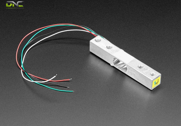
A load cell strain gauge is a foil resistor grid, bonded to the metal spring element of a load cell at a point of maximum strain, that changes resistance by 0.2 ohm in a 100 ohm gauge at a strain of 0.001. Four such gauges form a Wheatstone bridge, and the bridge delivers 1 to 3 mV/V at full load. Where the gauges sit and which bridge arm each one occupies decide which forces a load cell strain gauge reports and which forces it cancels.
Overload and bad mounting damage the spring element while the gauges keep reporting. Six decisions follow from that geometry: gauge versus cell, position, bridge arms, signal, failure location and specification. Plant engineers in Malaysia who buy load cells for scales, hoppers and checkweighers meet all six.
A Strain Gauge Senses Strain, and a Load Cell Is the Finished Transducer Built Around It
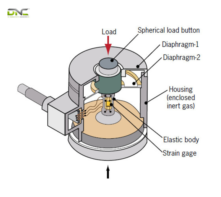
A strain gauge senses strain, and a load cell is the finished transducer that packs strain gauges, a metal body and a calibrated output into one housing. The strain gauge itself is the sensing element. Fine wire or foil lies in a grid on a flexible backing and is bonded to a surface. Stretching the grid makes the conductor longer and thinner, so resistance rises, and compression does the opposite, according to Wikipedia’s load cell entry.
The resistors in a load cell bridge usually measure 350 ohm, with 120 ohm and 1,000 ohm found less often. A strain gauge on its own reports strain, not force, and its raw resistance change needs signal conditioning. A load cell reports force or weight as a standardised electrical signal, calibrated at the factory and ready for indicators and PLCs, as one weighing distributor describes the split. The table below separates what each part measures, delivers and demands.
| Strain gauge | Load cell | |
| Measures | Strain (stretch or compression) at one surface | Force or weight through a designed path |
| Form | Foil or wire grid bonded to a structure | Spring element with gauges bonded, wired and sealed |
| Output | Raw resistance change, needs conditioning | Standardised signal in mV/V at rated load |
| Calibration | Left to the user | Done at the factory before shipping |
| Typical use | Stress analysis, testing, research | Scales, weighing systems, process control, overload monitoring |
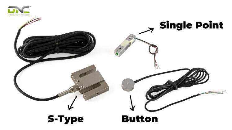
A bare strain gauge suits work where the structure itself acts as the elastic element, the geometry is custom, and the team can bond, wire and calibrate the gauges in-house, according to one sensor maker. A complete load cell suits work that needs a calibrated force value, known accuracy and overload ratings, and short integration time. A weighing station on a production line sits in the second group. The rest of this guide therefore treats the load cell strain gauge as an assembly, and DNC’s load cell and indicator range pairs that assembly with the instrument that reads it. Inside the assembly, the strain gauge reads only the strain that the metal body delivers to its grid.
A Strain Gauge Senses Strain, and a Load Cell Is the Finished Transducer Built Around It
A Strain Gauge Reads Only Where the Spring Element Concentrates Strain
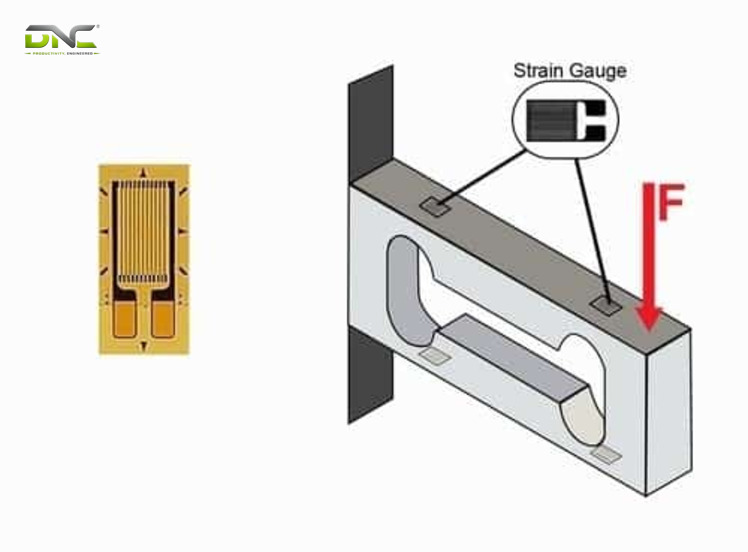
The spring element of a load cell concentrates strain in the places where the strain gauge sits, so the position of each gauge on the metal body defines what the load cell reports. One load cell supplier states the placement rule directly: the gauges belong at the points where the spring element sees the most strain under load, with the long axis of the grid along the principal axis of the force. The applied force then has to run completely along that axis for a correct reading.
The machined body exists to make that happen. A load cell focuses stress through the element where the gauges are bonded, and the body is a beam, an S-beam or a disk, shaped to fit a frame and to capture load in one direction. Cells are categorised and sold by that shape. One manufacturer builds the flexure from 17-4 stainless steel or aluminum, chosen for elasticity and for low hysteresis and creep. The same maker designs the strain element to expose more strain across the active area, which cuts the reproducibility error from off-axis loads.
Shape fixes the load path of a load cell, so shape also fixes how the cell mounts and what it tolerates. So gauge position is a design decision made in the metal, before any wiring exists. Mounting follows shape.
An S-beam load cell serves in-line duty only, and extraneous load, torque or moments disturb its reading strongly. A pancake cell resists off-axis loading. Single-point cells serve platform scales from 200 mm to 1,200 mm (120 cm / 47.2 in) on a side, and shear beam cells cover capacities from 100 kg (220 lb) to 50 t (50,000 kg / 110,231 lb), according to Wikipedia. For a hopper or a platform scale, the shape choice therefore selects which direction of force the cell resolves and which directions it treats as error.
Strain gauges bonded at angles to each other form a rosette. For non-axial strain, a rosette captures the components and the angle of maximum strain, which a single-axis gauge cannot. What strain each gauge sees depends on its position. The bridge arm that each gauge occupies then decides what the circuit does with that strain.
Bridge Arms Decide Which Strains Add and Which Strains Cancel
Bridge arms in a load cell decide which strains add and which cancel, because in a Wheatstone bridge strains on adjacent arms cancel and strains on opposite arms add, according to one load cell supplier. The full chain from applied force to calibrated reading is traced in the guide on how a load cell works. This section follows only the arm assignment.
Take a spring element loaded along its axis that also bends slightly. The strain gauge on the top face reads the load strain plus a tensile bending strain. The gauge on the bottom face reads the load strain plus a compressive bending strain of similar size. Wired on opposite arms, the two gauges sum their load strain and drop the bending part, so the bridge output reflects the load alone.
Temperature follows the same logic. Thermal strain adds equally to every strain gauge bonded to the same metal, and a load-free gauge placed next to a load-bearing gauge cancels that shared part. The sensing elements also sit in close proximity and in good thermal contact, so that temperature differences between them stay small, according to Wikipedia.
The bar-type load cell uses the rule the other way round. Four strain gauges read bending distortion on purpose, two in compression and two in tension, so strains of opposite sign on adjacent arms add into the signal. Both designs apply one rule to one circuit — only the gauge positions differ.
The number of active strain gauges sets the output of a load cell. The three configurations appear in the table below with the output formula from a force sensor maker, where GF is the gauge factor, ε the strain and Vexc the excitation voltage.
| Configuration | Active gauges | Output, Vout ≈ | What the arrangement does |
| Quarter bridge | 1 | (GF · ε / 4) · Vexc | Smallest output, cheapest build, easiest installation; temperature needs a separate answer |
| Half bridge | 2, on opposite arms | (GF · ε / 2) · Vexc | Cancels bending when the gauges sit on opposite faces of the element |
| Full bridge | 4 | GF · ε · Vexc | Largest output, cancels temperature effects, improves common-mode rejection |
Full bridges dominate commercial load cells for these three reasons, according to the same maker. A full bridge turns a resistance change of a fraction of an ohm into a signal in millivolts per volt.
Bridge Arms Decide Which Strains Add and Which Strains Cancel
The Bridge Delivers Millivolts per Volt, Not Ohms
A load cell bridge delivers millivolts per volt of excitation, not ohms, because the resistance change inside the strain gauge is far too small to read directly. Most metals have a gauge factor of about 2. For a 100 ohm gauge at a strain of 0.001, the largest resistance change is 0.2 ohm (200 milliohm), which falls inside the error of an ordinary ohmmeter, according to one load cell supplier. The bridge exists for that reason.
Wired into a bridge, that change becomes a voltage difference. The load cell output is rated in millivolts per volt of excitation at full load, typically 1 to 3 mV/V. A cell rated 2.96 mV/V and excited with 10 V (10,000 mV) delivers 29.6 mV (0.0296 V), according to Wikipedia. On battery-powered instruments, excitation drops to 5 V or lower; elsewhere it is usually 10 V, or 20 V, with a typical maximum near 15 V.
A four-wire load cell carries two excitation wires and two signal wires. A six-wire cell adds two sense wires, which let the controller compensate for the change in cable resistance caused by temperature. Long cable runs make that compensation matter, and one force sensor maker specifies six-wire cells when runs are long or temperature varies.
Then the millivolt signal reaches an amplifier or weighing indicator that supplies excitation, filters noise, amplifies the signal and converts it for a PLC or display. One sensor maker recommends calibrating the load cell together with its electronics as a single system, which is why the cell and the indicator belong in one specification. Reading that signal is the work of the indicator, and fixing what the signal contains is the work of the metal and the wiring.
Summary: What Position, Arms and Signal Fix Before an Indicator Is Fitted
Position, arms and signal fix the behaviour of a load cell strain gauge before any indicator is fitted. Gauge position decides which force axis the cell reads. Bridge arm assignment decides which strains cancel, among them bending and temperature.
The full bridge of a load cell outputs 1 to 3 mV/V at full load, from a resistance change of 0.2 ohm in a 100 ohm gauge. The indicator conditions and displays that signal, and it cannot recreate a cancellation that the metal and the wiring never made. The next failures all start in the metal or in the wiring.
Overload and Mounting Damage the Spring Element While the Strain Gauges Keep Reporting
Overload damages the spring element of a load cell first, and the strain gauges keep reporting whatever the yielded metal does. Within its rating, the metal deforms elastically and returns to its shape. Above the rating, the material may deform plastically, which produces a signal offset, loss of linearity, and difficulty or impossibility of calibration, according to Wikipedia. Severe cases damage the sensing element itself through delamination or rupture.
Strain beyond the safe load limit leaves a permanent change of shape in a load cell even when the device looks fine, according to one supplier. The zero-load resistance changes for good, and calibration can no longer bring the cell back to an accurate reading. The safe load limit differs from the breaking overload — both figures belong on the datasheet check. Yielded metal does not recover.
One force sensor maker sizes capacity as dead load plus live load, multiplied by a safety factor of 1.2 to 1.5 for static loads and higher for shock or vibration. Calibration cannot correct a yielded spring element, so no indicator setting restores the cell. The remedy sits at the load cell. Mounting passes force into that same metal, so the mounting comes next.
Off-Axis Load and Friction Report as Signal
Off-axis load and friction in the mounting report as signal, because the gauges respond to any strain at their position, wherever that strain comes from. The whole load force has to pass through the sensed part of the load cell, according to Wikipedia. In the mounting, friction may add offset or hysteresis. Wrong mounting may make the cell report forces along an undesired axis, which still correlate somewhat with the true load and confuse the technician.
A single-axis load cell resolves one dominant force direction well, so off-axis load is an error source to remove, according to a force sensor maker. The same maker advises trimming the corners of a multi-cell platform through a junction box. Wikipedia notes that pivots can replace some cells under symmetrical loads, which saves the cost of a cell and can significantly decrease accuracy. Setup is the riskiest moment. One manufacturer reports that setup causes most sensor damage and failure, and advises leaving the sensor plugged in during installation to watch the zero output for any shift.
Wiring, Moisture and Electrical Damage Imitate a Failed Gauge
Wiring, moisture and electrical damage imitate a failed strain gauge in a load cell, because each of them changes the bridge signal without bending the metal, and the output then looks like a drifting or dead sensor. Corroded wires raise the cable resistance, and moisture ingress creates parallel current paths. In both cases the signal develops an offset and accuracy is lost, according to Wikipedia. Lightning or arc welding near the cells may overstress the fine resistors of the strain gauges.
The table below pairs each load cell symptom with the part that is failing and the check that confirms it, using the troubleshooting guidance of two sources.
| Symptom | What is failing | Check that confirms it |
| Zero does not return after an overload event | Spring element yielded | Zero-load output changed for good; calibration no longer converges |
| Reading shifts with load position or reports another axis | Mounting, friction or off-axis load | Mounting bolts, alignment and friction path |
| Drift with moisture or temperature swings | Seals, cable or cable resistance | Seals, cable nicks, moisture ingress; six-wire sense for cable resistance |
| Offset after nearby lightning or arc welding | Gauge resistors overstressed | Bridge resistance against the datasheet; shunt calibration as a quick bridge health check |
| Intermittent output | Loose connector or electrical interference | Connectors and cable routing |
Bridge resistance out of specification often points to damaged strain gauges or cabling, according to one force sensor maker. Which cell technology avoids each of these failures depends on how fast the load changes.

Wiring, Moisture and Electrical Damage Imitate a Failed Gauge
Strain Gauge Load Cells Suit Static and Slow Loads, Which Is What Weighing Needs
Strain gauge load cells suit static and slowly changing loads, which is what weighing needs, and they track cyclic loads within their mechanical bandwidth. For fast impact events, one force sensor maker points to a piezoelectric sensor instead. A manufacturer of both types adds that piezoelectric cells combine high stiffness and fast dynamic response with a compact body, yet they measure less precisely than strain gauge cells because of higher linearity error and high drift. Speed is the trade-off.
Other principles exist as well. Capacitive load cells resist overload better than strain gauge cells because of their contactless measuring principle, according to Wikipedia. Hydraulic and pneumatic load cells also exist, according to one load cell supplier, so “load cell” names a function and not a single technology. The phrase “strain gauge load cell” names the technology that dominates weighing.
Strain gauges inside those cells come in four technologies, according to one force sensor maker. The list below names them in the order that the maker gives.
- Bonded metal foil is stable, widely used and has good temperature behaviour.
- Semiconductor gauges have a much higher gauge factor and are more temperature-sensitive.
- Thin-film gauges, vacuum-deposited, give premium stability and repeatability.
- MEMS gauges, micro-machined, are compact and increasingly common inside digital and wireless cells.
A single-axis load cell reads one direction of force. Robotic wrists use six-axis force-torque sensors, built on the same gauge-and-bridge principle, to measure three forces and three moments at once, so off-axis load is part of the measurement there and an error in a weighing cell. For a weighing line, the specification therefore turns on the spring element and the bridge, with the gauge material a secondary choice.
Specifying a Strain Gauge Load Cell Starts With the Load Path
Specifying a strain gauge load cell starts with the load path, because the path decides the spring-element shape, the capacity and the mounting before any datasheet figure is compared. In a DNC weighing specification, the load path is fixed first and the indicator is matched to the cell second. Path first, indicator second. The five steps below follow that order, with figures from the sources named in this guide.
- Define the load path as tension, compression or both, and account for side loads and moments.
- Size the capacity at dead load plus live load, multiplied by a safety factor of 1.2 to 1.5 for static loads.
- Choose mounts that align the force vector, such as rocker columns or foot mounts, and trim corners through a junction box on multi-cell platforms.
- Choose six-wire cells for long cable runs or variable temperature.
- Calibrate the cell and its electronics together, and plan recalibration yearly as a baseline, more often in harsh or high-cycle use, according to two manufacturers.
Each step ties back to an earlier section: the path to gauge position, the mounts to off-axis load, the wiring to the bridge signal. Engineers at DNC Automation specify load cells, weighing indicators and checkweigher integration for Malaysian production lines. To review the load path of a weighing station before the capacity is chosen, talk to our engineers.
Specifying a Strain Gauge Load Cell Starts With the Load Path
Frequently Asked Questions About the Load Cell Strain Gauge
Buyers of a load cell strain gauge ask six questions most often, and each answer below stands alone, in the order from definition to recalibration.
What is the difference between a load cell and a strain gauge?
A strain gauge senses strain, while a load cell converts force into a calibrated electrical signal. The gauge is a foil or wire grid that changes resistance when stretched or compressed. The load cell combines strain gauges, a machined spring element, wiring and a seal in one device, with an output of 1 to 3 mV/V at rated load.
How many strain gauges does a load cell have?
A full-bridge load cell has four active strain gauges, a half bridge has two, and a quarter bridge has one. Commercial cells use full bridges for the largest output, temperature cancellation and common-mode rejection, according to a force sensor maker. The four gauges occupy the four arms of one Wheatstone bridge.
Where is the strain gauge placed on a load cell?
The strain gauge sits at the point where the spring element sees the most strain under load, with its long axis along the principal axis of the force. A rosette places gauges at angles to one another to capture non-axial strain.
Why does a strain gauge load cell use a Wheatstone bridge?
A strain gauge load cell needs a Wheatstone bridge because a 100 ohm gauge changes by only 0.2 ohm at a strain of 0.001. The bridge sets the gauge against matched resistors, so the output signal keeps the scale of the quantity measured. Temperature strain adds equally to every arm and cancels.
Does a bare strain gauge replace a load cell?
A bare strain gauge replaces a load cell only where the structure itself acts as the elastic element and the team calibrates the gauges in-house. Everywhere else, the load cell supplies a calibrated force value with known accuracy and overload ratings. Production weighing stations belong in that second group.
How often does a strain gauge load cell need recalibration?
A strain gauge load cell needs recalibration at a defined interval, and two manufacturers give yearly as the baseline. Harsh environments and high-cycle use call for shorter intervals. Calibrating the cell together with its indicator confirms the whole measuring chain.
- 2 views
- 0 Comment
Recent Comments