


How Does a Load Cell Work | DNC Automation Malaysia
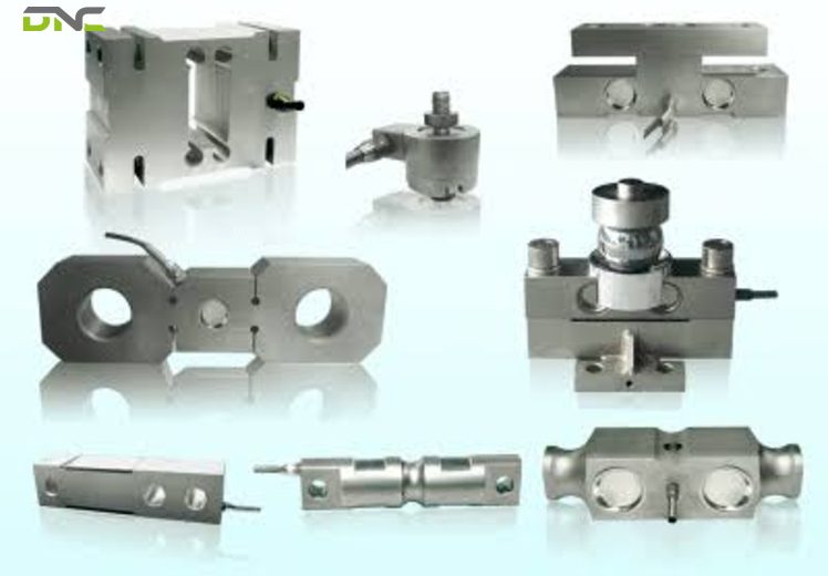
A load cell is an electro-mechanical transducer that converts an applied force into a proportional electrical signal. Inside the sensor, a machined spring element of alloy steel, 17-4 stainless steel, or aluminium deforms under load. Bonded foil strain gauges track that deformation as a change in electrical resistance. Four gauges wired into a Wheatstone bridge convert the resistance change into a differential output measured in millivolts per volt of excitation. A signal conditioner then amplifies, filters, and digitises that output for a PLC, a DAQ module, or a weight indicator. Every industrial scale, checkweigher, batching hopper, and force test stand in a Malaysian factory depends on this same four-stage measurement chain inside the load cell.
The Working Principle of a Load Cell in Four Stages
From a measurement chain point of view, a load cell works by converting mechanical deformation into a proportional voltage in four sequential stages. Force enters the sensor body. The body deforms. Bonded strain gauges register that deformation electrically. A bridge circuit outputs the result as a voltage.
The four stages of load cell operation are listed below in fixed order.
- Load transfer.One end of the load cell is anchored to a rigid structure while the opposite live end receives the applied force.
- Elastic deformation.The spring element flexes by a controlled, repeatable amount – typically 0.1 mm to 1 mm (0.004 in to 0.04 in) at full scale.
- Resistance change.Foil strain gauges bonded at the maximum-strain zones stretch or contract, altering their electrical resistance in proportion to the strain.
- Voltage output.A Wheatstone bridge converts the resistance imbalance into a differential voltage, expressed in mV/V of the applied excitation.
Deformation at stage two stays invisible to the naked eye. Flintec describes the effect as a fishing rod bending under a hooked fish – the rod is fixed in the hands while the load pulls the free end, and a heavier load produces a larger bend. That elastic behaviour is the entire basis of the measurement, which makes the metallurgy of the spring element as important as the electronics attached to it.
The Working Principle of a Load Cell in Four Stages
Inside the Load Cell: Spring Element, Strain Gauge, and Wheatstone Bridge
From a component point of view, a strain gauge load cell contains three functional parts: a machined spring element, bonded foil strain gauges, and a Wheatstone bridge circuit. The spring element carries the load. The gauges sense it. The bridge reports it.
The Spring Element Carries and Shapes the Load
The spring element carries the applied load and shapes where strain concentrates, working as a precisely machined metal body – also called the flexure – that deforms predictably along one axis. Manufacturers restrict the material choice to a narrow group of alloys, since the metal must combine high strength, linear elasticity, and corrosion resistance.
Anyload identifies high-grade alloy steel, stainless steel, and aluminium as the standard options. FUTEK specifies aerospace-grade 17-4 stainless steel and aluminium for its sensor flexures, citing low hysteresis and low creep across a wide temperature range. Encardio-Rite uses hardened martensitic stainless steel in columnar elements rated from 200 kN to 12,500 kN.
Geometry does the rest. Machining, surface treatment, and heat treatment concentrate strain into well-defined zones, and the strain gauges are bonded precisely to those zones.
The Strain Gauge Converts Deformation Into Resistance Change
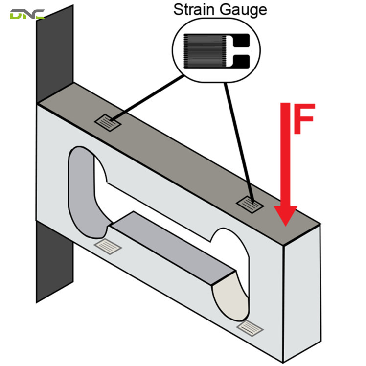
A strain gauge is a thin metallic foil pattern bonded to a flexible carrier, whose electrical resistance changes in proportion to mechanical strain. The foil follows a tight zigzag path, which maximises conductor length inside a small footprint.
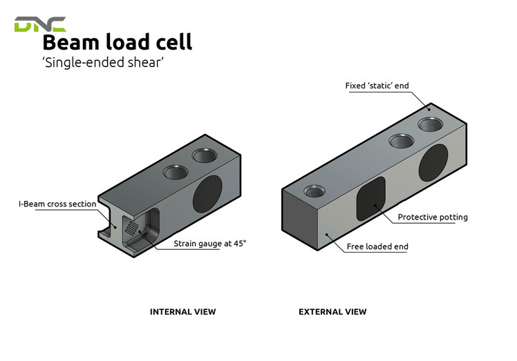
That zigzag geometry creates directional sensitivity. The gauge responds strongly to stretch and compression along its length and weakly across its width, so engineers can align it to a chosen load axis. Shear beam load cells exploit this by positioning gauges at 45 degrees to the loading axis, maximising detection of shear strain.
Resistance rises when the foil elongates and falls when it contracts. A 350-ohm gauge is the industry-standard building block, and Encardio-Rite wires eight 350-ohm gauges into a 700-ohm bridge, or sixteen into a 1,400-ohm bridge, spacing them evenly around the circumference to cancel eccentric loading effects.
The Wheatstone Bridge Produces the Measurable Voltage
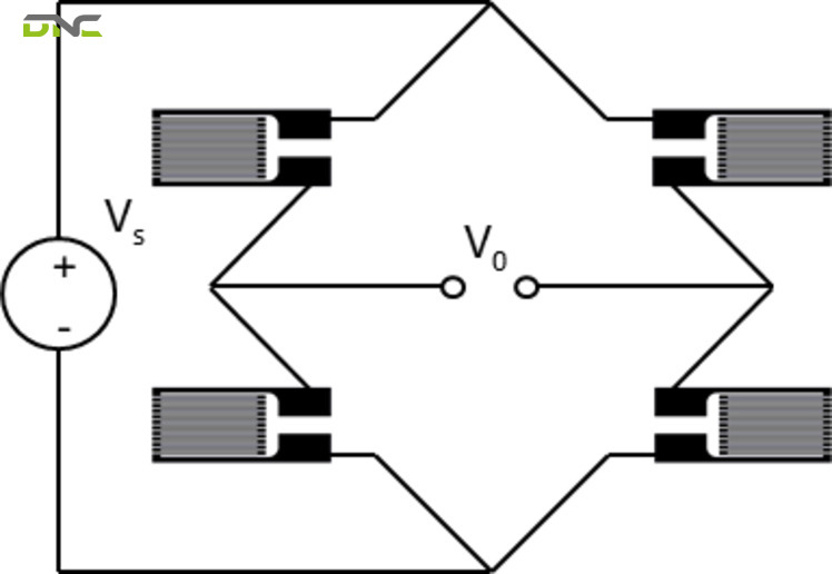
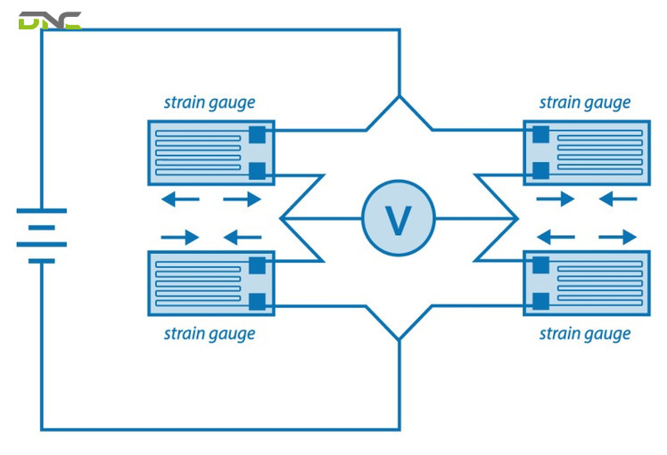
The Wheatstone bridge is a four-arm resistive circuit that converts a small resistance change into a differential output voltage. An excitation voltage feeds two opposite corners of the bridge. The output is read across the other two corners.
At zero load the bridge sits balanced and the output voltage reads zero. Any strain in the gauges unbalances the arms, and the resulting differential voltage tracks the applied force. HBM notes that most strain gauge load cells use four gauges in exactly this configuration.
The bridge earns its place for two reasons beyond signal generation. It compensates for temperature-induced resistance drift, and it resolves resistance changes far too small for a single gauge to report reliably. Output stays low in absolute terms – millivolts, not volts – which is why signal conditioning sits between every load cell and the control system reading it.
Signal Conditioning Turns Millivolts Into a Usable Reading
Signal conditioning is necessary because a load cell outputs a ratiometric millivolt reading too weak for a PLC or DAQ to read directly. Encardio-Rite specifies roughly 1.5 mV/V full-scale output from a bridge excited at 10 VDC. A full-bridge sensor can produce signals down in the nanovolt-to-millivolt band.
A load cell amplifier performs four jobs in sequence, and each one is listed below.
- Excitation supply.The amplifier feeds a stable voltage to the bridge – FUTEK’s USB data acquisition systems supply amplified sensors up to 24 VDC.
- Electronic filters strip out electrical noise and ripple; FUTEK’s IAA series analog conditioners allow bandwidth selection from 100 Hz to 50,000 Hz.
- Millivolt-level output is raised to a level a DAQ or PLC analog input can resolve.
- Signal conversion.An analog-to-digital converter or scaling stage delivers 0–10 VDC, ±10 VDC, 4–20 mA, or a digital output over SPI, UART, USB, RS232, or RS485.
Select the amplifier at the same time as the load cell. Compatibility between excitation requirement, output range, and controller input decides whether the measurement chain works on commissioning day or becomes a wiring problem discovered on site.
Signal Conditioning Turns Millivolts Into a Usable Reading
Summary of the Load Cell Measurement Chain
The load cell measurement chain, in summary, runs from applied force to a calibrated reading in four linked conversions. Force applied to the spring element produces controlled elastic deformation of 0.1 mm to 1 mm at full scale. Bonded foil strain gauges at the high-strain zones convert that deformation into a resistance change, typically from 350-ohm elements. Four or more gauges wired as a Wheatstone bridge translate the resistance imbalance into a differential voltage of roughly 1.5 mV/V at 10 VDC excitation. A signal conditioner supplies excitation, filters noise, amplifies the millivolt signal, and converts it to 4–20 mA, 0–10 VDC, or a digital protocol your PLC accepts. Body geometry decides which forces a given load cell type is built to measure, and certification class and mounting method then determine how much of that theoretical accuracy survives in a running production line.
Load Cell Types and the Forces They Are Built to Measure
Load cell types differ in body geometry and in the direction of the forces they measure, while sharing the identical strain gauge working principle. Flintec groups the market into four core categories, and FUTEK extends the list with geometries built for confined or multi-axis applications.
The common strain gauge load cell types include the following configurations:
| Type | Load direction | Typical characteristic |
| Beam (single-ended) | Bending | Cantilever action – fixed at one end, deflects at the other |
| Double-ended beam | Bending | Fixed at both ends, loaded at the centre |
| Single point | Compression, off-centre | Maintains accuracy when load is placed away from centre |
| Compression | Push, single axis | Column geometry for high-capacity static loads |
| Tension (S-type) | Pull | Load suspended from the foot; many also read compression |
| Canister / column (in-line) | Push and pull | Threaded, high stiffness, minimal mounting clearance |
| Load button | Compression | Miniature footprint for tight spaces |
| Pancake / thru-hole | Compression, tension | Low profile, bolt-through mounting |
| Multi-axis | ±Fx, ±Fy, ±Fz plus moments | Force-torque sensing in all spatial directions |
Load Cell Types and the Forces They Are Built to Measure
Capacity ranges span an extreme spread. FUTEK lists sensors from 10 grams (0.35 oz) to 100,000 pounds (45,359 kg / 45.4 tonnes), HBM supplies compression load cells with maximum capacities up to 50 tons (50,000 kg / 110,231 lb), and Encardio-Rite builds civil-engineering columns rated to 12,500 kN (approximately 1,274 tonnes-force).
Not every load cell uses strain gauges. HBM notes that hydraulic and pneumatic load cells remain available. Piezoelectric sensors take a different route entirely: two crystal disks with an electrode foil between them generate an electrical charge under applied force. FUTEK positions piezo sensors as the choice for fast dynamic measurements of small forces, and strain gauge sensors as the choice for long-term monitoring, because piezo units carry higher drift and higher linearity error.
Accuracy, Error Sources, and What the Specification Sheet Means
Load cell accuracy, as each error source on a specification sheet defines it, is the smallest force change that produces a linear, repeatable variation in output voltage. Every line on that sheet describes one particular way linearity or repeatability degrades.
The error terms that appear on a load cell datasheet are defined below.
- Maximum deviation of the real calibration curve from a straight line between no-load and rated output, expressed as a percentage of rated output. High-precision units reach ±0.02% RO.
- Maximum difference between output readings for repeated identical loads under identical conditions – also ±0.02% RO on precision sensors.
- The lag between loading and unloading curves, measured at half rated output as the difference between an increasing-force reading and a decreasing-force reading.
- Output drift under a constant applied load held over time.
- Zero offset.Output at true zero force sitting above or below the ideal zero, plus the sensor’s ability to hold that zero as conditions change.
- Temperature shift.Change in span and in zero balance caused by temperature variation across the sensor body.
Extraneous loads sit outside this list and cause more field failures than any datasheet term. Off-axis force and bending moments raise combined stress, accelerate fatigue, and degrade accuracy. FUTEK advises operating at 50% or less of rated capacity for endurance applications, or specifying a fatigue-rated sensor, and rates its strain gauge sensors for up to a billion fully reversed cycles.
Environmental sealing protects all of it. Most load cells are potted, meaning internal cavities are filled with epoxy or resin that shields the circuit from humidity and helps dissipate heat. Hermetically sealed units use a fully welded enclosure – Encardio-Rite electron-beam welds a stainless diaphragm to create an internal vacuum near 1/1000 Torr. An IP67 rating means the unit withstands submersion in one metre (1,000 mm / 3.28 ft) of water for up to 30 minutes. None of these error figures carry weight in trade or audit without certification and a calibration record behind them.
Accuracy, Error Sources, and What the Specification Sheet Means
Certification and Calibration Requirements
Certification and calibration requirements split into two obligations: a load cell used in trade carries legal-for-trade certification from a recognised metrology authority, and every load cell in service holds a current calibration record. The International Organization of Legal Metrology governs these rules internationally, and the National Type Evaluation Program committee performs the equivalent function in the United States.
Commercial weighing scales typically carry OIML C3 class certification. Load cells sold without OIML or NTEP approval are labelled general purpose, and Flintec notes that general purpose units often deliver comparable accuracy where legal-for-trade rules do not apply. Facilities handling flammable gases, solvent vapours, or fine organic dusts such as flour need ATEX or FM certification for hazardous-area use.
Calibration corrects the error terms rather than eliminating them. A calibration run compares sensor output against reference weights, then adjusts zero offset and span against an ideal linear response, while also checking hysteresis, repeatability, and temperature shift. FUTEK reports independent offset and span calibration to a precision of 200 µV out of 10 V, under procedures compliant with ISO 17025 and accredited to ANSI/NCSL Z540-1.
Calibrate the load cell together with its electronics. The sensor, signal conditioner, cabling, and connectors behave as one measurement system, and calibrating them separately leaves the system error uncorrected. FUTEK recommends yearly recalibration under continuous use, and more frequent intervals for critical applications or harsh environments. A calibration certificate still describes bench conditions, which installation either preserves or destroys.
Installation Determines Whether the Load Cell Performs to Specification
Installation determines whether a load cell performs to its specification, because a load cell is only as good as its mounting. Most sensor damage and most failures occur during setup rather than during operation, which puts installation ahead of datasheet accuracy in real-world measurement quality.
Buying a higher-accuracy load cell rarely fixes a weighing problem. Misalignment, structural vibration, and cable strain distort a reading far more than a 0.02% nonlinearity figure ever will. Procurement teams evaluate load cells on capacity and unit price; commissioning engineers evaluate them on mounting tolerance, load path, and cable routing.
The load cell installation practices that protect measured accuracy are listed here.
- Anchor the fixed end to a rigid structureand leave the live end genuinely free to deflect, since even slight constraint skews the reading.
- Never carry or pull the sensor by its cable, and secure the cable so movement does not couple into the load path.
- Respect the cable bend radius– no tighter than ten times cable diameter in dynamic applications, and two to three times diameter for a permanent static bend.
- Keep the sensor powered during installationso output can be monitored for zero shift or overload as it happens.
- Stay inside the rated load range, using built-in overload protection – some FUTEK models tolerate 10x direct inline overload – as a safety margin rather than an operating allowance.
Alignment and load path decide whether a sensor rated at ±0.02% delivers anything close to that figure once bolted into a moving machine. That distinction matters most where the load cell stops being a bench instrument and becomes a component inside a production line.
Installation Determines Whether the Load Cell Performs to Specification
Load Cells Inside Automated Production Lines
Inside an automated production line, a load cell functions as a real-time process control input rather than a standalone weighing instrument. The sensor sits inside a subsystem, and its output drives a decision that a PLC executes in milliseconds.
Four load cell measurement points recur across Malaysian manufacturing plants, and each one is described below.
- A load cell platform under a moving conveyor belt weighs every pack in motion, and the PLC rejects out-of-tolerance units downstream. DNC Automation integrates this measurement into automated inspection systems alongside machine vision and metal detection.
- Batching and dosing.Hopper-mounted compression load cells report ingredient mass in real time, and the controller closes the feed valve at target weight – the standard control loop in food, beverage, and oleochemical plants.
- Palletising and end-of-line verification.Weight confirms that a completed pallet matches its expected case count before it enters storage.
- Robotic force sensing.Multi-axis sensors report force and torque in all spatial directions, giving collaborative robots the force feedback that assembly and insertion tasks require.
Integration is where the specification work concentrates. A load cell mounted on a conveyor system inherits every vibration mode of the frame, so the mechanical design, the filter bandwidth on the amplifier, and the PLC sampling rate must be specified together rather than in sequence. DNC’s engineers treat the mounting structure, sensor, conditioner, and controller as a single deliverable during commissioning across a project base exceeding 1,000 installations.
Weight data also feeds upward. Once load cell readings flow into a smart manufacturing layer through SCADA and IoT connectivity, the same signal that rejects an underweight pack also produces yield reports, batch traceability records, and giveaway analysis. That data path carries direct relevance under NIMP 2030, where Industry 4.0 grants favour Malaysian manufacturers that can demonstrate connected, instrumented production.
If your facility is specifying weighing, checkweighing, or force measurement as part of a broader automation project, DNC’s engineers can size the load cell, the signal conditioning, and the control interface as one system. Bring your load profile and line speed to the specification stage, and Get a Free Consultation before the mechanical design is frozen.
Load Cells Inside Automated Production Lines
Frequently Asked Questions
The questions asked most frequently about load cells cover the working principle, the distinction from a bare strain gauge, output levels, calibration intervals, and type selection – the points engineers raise when specifying force measurement for a production line.
What is the working principle of a load cell?
A load cell works by converting mechanical force into a proportional electrical signal through elastic deformation. Applied force flexes a machined spring element, bonded foil strain gauges change resistance in proportion to that strain, and a Wheatstone bridge converts the resistance imbalance into a differential output voltage in mV/V.
What is the difference between a load cell and a strain gauge?
A strain gauge is a single resistive sensing element, while a load cell is a complete transducer containing four or more strain gauges arranged in a Wheatstone bridge on a machined spring element. A strain gauge alone reports strain on a surface. A load cell reports force, because its body geometry and calibration relate that strain to a known load.
Why do load cells use a Wheatstone bridge circuit?
Load cells use a Wheatstone bridge because it resolves resistance changes too small for a single gauge to measure and compensates for temperature drift. The bridge sits balanced at zero load and outputs zero voltage. Strain unbalances the arms and produces a stable, repeatable differential voltage proportional to the applied force.
What output does a load cell produce?
A load cell produces a ratiometric millivolt signal of 1.5 mV/V of excitation at full scale. A bridge excited at 10 VDC therefore delivers roughly 15 mV at rated load. A signal conditioner converts that output to 0–10 VDC, 4–20 mA, or a digital protocol such as RS485 for the PLC.
How often should a load cell be calibrated?
A load cell under continuous industrial use is calibrated yearly, and more often in critical applications, harsh environments, or after any suspected overload. Calibrate the sensor together with its amplifier, cabling, and indicator, since these components behave as one measurement system.
Which load cell type suits a weighing application?
Select the load cell type by load direction and mounting constraint. Single point load cells suit platform scales where load placement varies, compression and canister types suit high-capacity static loads such as tank and hopper weighing, S-type units suit suspended tension measurement, and multi-axis sensors suit robotic force-torque feedback.
- 12 views
- 0 Comment
Recent Comments