


Load Cell Calibration Guide | DNC Automation Malaysia
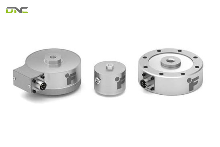
Load cell calibration establishes a documented, traceable relationship between the electrical output of a load cell and the actual force applied to it. The work follows a defined sequence: preload the sensor, capture the zero point, apply certified reference forces in ascending steps, compare output against expected values, then compute the gain and offset that convert a raw signal into a weight reading. Which tolerance applies depends on the standard governing the application – ASTM E74 for force measurement instruments, ISO 376 for transducers that verify testing machines, and OIML R 60 for legal weighing. This guide covers the procedure, the standards, the values printed on a calibration certificate, how intervals are set, and what changes when the load cell sits inside an automated production line rather than on a laboratory bench.
What Load Cell Calibration Establishes
Load cell calibration establishes what the sensor reports at a given force by comparing its measurement result against a calibration standard. The output is a documented characteristic curve for that individual unit, together with the uncertainty of the reading at each load step. A calibrated sensor carries characteristic values specific to that individual unit, which are in most cases more precise than the datasheet figures that apply to an entire model series.
Two data sets appear on every accredited calibration. As-found measurements record how the instrument performed on arrival, before any adjustment. As-left measurements record performance after calibration is complete. The difference between them documents how far the load cell drifted during the previous interval, which is the primary evidence for deciding whether the calibration schedule is set correctly.
Two misconceptions cause most calibration problems on a factory floor, and both are worth correcting before the procedure itself. The first is that a load cell holds its accuracy until it visibly fails. Contrary to that assumption, drift produces no symptom an operator can see. Drift is not a defect and produces no visible symptom – mechanical wear, repeated loading cycles, temperature exposure, humidity, and vibration all shift a sensor away from its original characteristic curve while it continues to display plausible numbers. The second is that a calibration certificate covers the reading on the operator’s screen. It covers the sensor only, under controlled laboratory conditions, and the installed weighing system carries additional error that no certificate describes.
Calibration measures that shift and either corrects it or documents that no correction was required.
The stakes are quantifiable. A Morehouse Instrument Company study of 171 load cells found a 5.26% failure rate at the 10% capacity test point, the highest of any range tested across 513 calibration samples. Instruments operating past their due date report forces several tenths of a percent away from true values, which is enough to affect product acceptance decisions and the validity of quality documentation.
What Load Cell Calibration Establishes
The Load Cell Calibration Procedure in Six Steps
The load cell calibration procedure applies known reference forces in a controlled sequence and derives the correction factors that map raw output to engineering units. The six steps below run in fixed order.
- Preload the sensor.The load cell is exercised at or near its maximum calibration force before data collection begins. Preloading settles the mechanical assembly and removes the effect of first-cycle set.
- Capture the zero point.With no load applied, the output at rest is recorded. This becomes the offset, the baseline the system subtracts from every subsequent reading.
- Apply known reference forces.Certified masses or a reference transducer generate forces in ascending steps across the intended working range.
- Compare output against expected values.At each step the recorded output is set against the value the reference standard reports. Deviations are logged for every point rather than averaged into a single figure.
- Compute gain and offset.Gain converts the raw ratiometric output into a weight or force value. Offset removes the zero reading. Together these two parameters define the conversion the indicator or PLC applies.
- Verify and document the as-left condition.The calibrated system is re-checked against the reference to confirm the correction holds, and the results are recorded on the certificate.
Offset behaves differently from gain in service. Gain is a property of the mechanical and electrical assembly and stays fixed between calibrations. Offset shifts with mounting stress, accumulated material on a weighing platform, and temperature, which is why taring recalculates the zero point routinely without constituting a recalibration.
Two-Point Calibration Trades Accuracy for Speed
Two-point calibration adjusts the system at two reference points, normally zero and one load value near the top of the working range. The method is fast and adequate where the load cell operates close to a single known weight. It carries a defined limitation: a straight line drawn through two points cannot describe non-linearity elsewhere in the range. Error between those two points goes unmeasured.
Multipoint Calibration Characterises the Full Range
Multipoint calibration applies loads at several points across the capacity of the sensor and evaluates the deviation at each one. ISO 376 calibrations use eight to ten steps up to the maximum calibration force. The approach costs more time and produces a characteristic curve that reflects real behaviour across the range, which matters when a weighing point handles loads varying from a few percent of capacity to full scale.
The Load Cell Calibration Procedure in Six Steps
The Three Standards That Govern Load Cell Calibration
Three standards govern load cell calibration across industrial, scientific, and commercial applications, and the applicable standard determines the accuracy class to specify, the test method to require, and which laboratories are qualified to issue a conforming certificate. A certificate issued under one standard does not satisfy a requirement written against another.
| Standard | Scope | Accuracy classes | Typical application |
| **ASTM E74** | Force-indicating instruments | Class AA (0.05% max loading error), Class A (0.10%) | Reference and working force standards, universal testing machines |
| **ISO 376** | Force-proving instruments verifying uniaxial testing machines | 00, 0.5, 1, 2 (00 highest) | Transfer standards, tensile and compression machine verification |
| **OIML R 60** | Load cells in legal metrology | C1 through C6 | Platform scales, floor scales, weighing for trade |
ASTM E74 also defines the lower limit of the verified range – the minimum force below which the instrument no longer holds its stated accuracy class. A load cell rated Class A may meet that class only above 2% of rated capacity. Any application that measures near the bottom of the range needs this limit checked before the sensor is specified, because the certificate accuracy does not extend below it.
Under OIML R 60 the class number indicates the minimum number of verification intervals in thousands, so a Class C3 load cell supports at least 3,000 scale verification intervals. C3 is the common specification for commercial weighing instruments subject to regulatory oversight. This standard governs load cells used in trade and customs applications rather than industrial force measurement, and the distinction decides which certificate an inspector will accept.
Inside an ISO 376 Calibration: Preloading, Six Runs, and Rotation
An ISO 376 load cell calibration runs a structured sequence of six measurement runs performed in three mounting positions, which is what separates it from a working-standard calibration and what produces its tighter uncertainty figures.
The sequence begins with preloading the sensor three times, each time at the maximum calibration force. The transducer is then loaded to maximum in eight to ten increasing steps, unloaded, and the identical sequence repeated in an unchanged mounting position. These first two runs are recorded as R1 and R2.
The sensor is then dismounted, rotated by 120 degrees, and reinstalled. After preloading again to maximum force, run R3 applies increasing load steps and run R4 records the decreasing steps from the highest point, using the same load values on the way down. A second rotation of 120 degrees follows, and runs R5 and R6 repeat that increasing and decreasing pattern in the third mounting position. A creep measurement closes the procedure after the final unloading.
Rotation is the reason this method reports reproducibility. Running the same load steps in three mounting orientations exposes how much the output depends on how the sensor was installed, which a single-position calibration cannot detect. For a load cell that will be mounted, removed, and remounted during service, that figure carries direct operational meaning.
Inside an ISO 376 Calibration: Preloading, Six Runs, and Rotation
What Your Calibration Certificate Documents
Your calibration certificate documents more than a pass or fail verdict. It records a set of characteristic values calculated at every load step, and each one describes a different aspect of sensor condition.
- Repeatability– the difference in output at the same load step in an unchanged mounting position. It feeds directly into the expanded uncertainty reported on the certificate.
- Reproducibility– the difference in output at the same load step across different mounting positions.
- Hysteresis (reversibility)– the difference in output at the same force depending on whether that force was reached while loading or unloading. Elevated values indicate mechanical friction or structural wear inside the sensor body.
- Creep– the change in output while a constant force is held. Worsening creep across successive calibrations indicates sensor ageing or damage.
- Zero error– the deviation of the zero point measured before and after a full loading and unloading cycle.
- Interpolation error– the difference between the real characteristic curve of the sensor and the fitted curve used to convert output to force.
Temperature is documented because it changes the result. A 10°C (18°F) shift away from calibration temperature introduces zero shift errors of 0.01% to 0.03% of rated output in typical strain gauge designs, which is why accredited laboratories control ambient conditions and record the calibration temperature on the certificate.
Traceability is documented separately. Each measurement references force standards whose own certificates trace back to national measurement standards, and ISO/IEC 17025:2017 requires that chain to be complete. Two checks belong in any incoming certificate review: confirm that the reference standard certificates listed are still current, and confirm that the laboratory scope of accreditation names force measurement explicitly rather than by implication.
Measurement Uncertainty and the 4:1 Test Uncertainty Ratio
Every certificate from an ISO/IEC 17025:2017 accredited laboratory states an expanded measurement uncertainty – the range within which the true force value is expected to lie, normally at 95% confidence with a coverage factor of k=2. The figure is the deciding factor in whether a calibration is adequate for the tolerance the application requires.
The governing metric is the Test Uncertainty Ratio. TUR equals the acceptable tolerance of the instrument divided by the measurement uncertainty of the calibrating laboratory. ANSI/NCSL Z540.3 requires a minimum ratio of 4:1. A load cell that must hold ±0.1% therefore needs a laboratory whose stated uncertainty is ±0.025% or better at the relevant capacity.
This is where supplier qualification most often fails. Accreditation status alone does not establish capability, because a laboratory holding valid ISO/IEC 17025:2017 accreditation with a force measurement uncertainty of ±0.3% cannot produce a 4:1 ratio against a ±0.1% tolerance requirement. The published Calibration Measurement Capability for force at the specific capacity is the figure to request before a laboratory is approved.
Uncertainty also depends on how the reference force was generated. Deadweight machines apply force through stacks of precisely characterised masses and reach uncertainties of roughly 0.002% to 0.01% of applied force, which qualifies them for ASTM E74 Class AA work. Their practical ceiling sits near 2 MN (450,000 lbf). Hydraulic reference machines paired with pre-calibrated transfer transducers extend to 50 MN (25 times that ceiling) and beyond for structural and heavy industrial capacities, and build-up systems combining several reference transducers cover in-situ calibration of permanently installed load cells.
Measurement Uncertainty and the 4:1 Test Uncertainty Ratio
Summary of the Calibration Requirements Covered So Far
The load cell calibration requirements covered so far reduce to four decisions taken before any interval is set. The applicable standard comes first – ASTM E74 for force-indicating instruments, ISO 376 for transducers verifying testing machines, OIML R 60 for legal weighing – because it fixes the accuracy class and the test method. The calibration method follows from required uncertainty and capacity: deadweight machines at 0.002% to 0.01% up to roughly 2 MN (450,000 lbf), hydraulic reference machines above that, build-up frames where the sensor stays in place. The certificate then reports repeatability, reproducibility, hysteresis, creep, zero error, and interpolation error at every load step, with as-found and as-left data documenting drift. The expanded uncertainty on that certificate must clear a 4:1 ratio against the tolerance the application requires. Interval determination, covered next, depends on the as-found history these certificates accumulate.
Load Cell Calibration Intervals and How They Are Set
Load cell calibration intervals have no universal frequency behind them. NIST recommends no fixed interval for measuring instruments, and quality standards replace prescribed schedules with risk-based requirements. Annual calibration is the standard starting point for industrial load cells, adjusted from there using the instrument’s own history.
ISO 9001:2015 Clause 7.1.5.2 requires measuring equipment used in quality-critical processes to be calibrated at specified intervals with documented evidence that it stays fit for use throughout. The clause sets no frequency. AS9100D requires planned intervals with emphasis on maintaining measurement confidence, and most aerospace programmes default to twelve months for active load cells given the safety implications of force data.
ANSI/NCSL Z540.3 makes the reasoning explicit through probability: the interval must maintain at least an 85% probability that the instrument remains in tolerance at the end of the period. That rule works in both directions. Frequent out-of-tolerance as-found findings call for a shorter interval. Consistent in-tolerance results across several cycles support extending the interval, provided the justification is documented.
Six Conditions That Require Early Recalibration
Six conditions require early recalibration regardless of where the instrument sits in its scheduled cycle, because scheduled intervals assume normal operating conditions. Each one overrides the schedule.
- Overload events.Most specifications set an overload threshold between 125% and 150% of rated capacity. Exceeding it permanently deforms the strain gauges or alters the geometry of the sensor body. Normal-looking operation afterwards proves nothing, because sensitivity and linearity shift in ways only calibration detects.
- Physical shock or drop.Mechanical impact below the overload threshold still shifts zero balance. Any documented drop or collision warrants a calibration check before the instrument returns to service.
- Out-of-tolerance as-found findings.A load cell that arrives out of tolerance raises questions about every measurement taken during the previous interval, and a documented impact review of the affected results is required under ISO 9001, AS9100, and ISO 13485.
- Creep drift beyond specification.Output drift under a constant held load that exceeds the manufacturer creep specification means the performance characteristics have changed. Where drift has worsened significantly, repair or replacement precedes any useful recalibration.
- Temperature excursion outside the operating range.Process heat, cold storage, and outdoor installation drive load cells past their specified range and cause permanent changes in zero balance or span sensitivity that routine operation does not reveal.
- Repair, replacement, or modification of an associated component.Changing a cable, connector, or signal conditioning amplifier changes the characteristics of the measurement system, and the system as modified requires calibration before it goes back into service.
Six Conditions That Require Early Recalibration
Sensor Calibration and System Calibration Answer Different Questions
Sensor calibration and system calibration answer different questions about the same measurement point. A laboratory certificate describes the load cell alone, and it does not describe the installed weighing system that the operator actually reads. Laboratory calibration reports how the sensor behaves against traceable reference forces under controlled ambient conditions. System calibration reports what the operator on the line actually reads once that sensor is bolted into a frame and wired through a junction box, an amplifier, and a controller.
The gap between them is mechanical and electrical. Mounting stress, non-vertical load introduction, piping and cable pull on a hopper, and summing errors across several load cells in one junction box all affect the delivered value without affecting the certificate. A load cell that passed calibration at 0.05% loading error contributes very little to a system reading 0.5% out because the vessel it supports is braced against an adjacent structure.
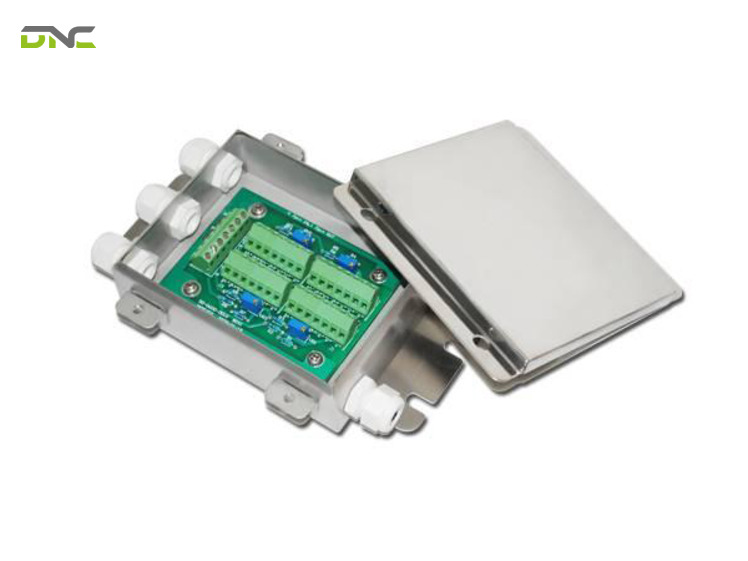
This is why the calibration record for an installed weighing point covers the sensor, the cabling, the summing junction, the amplifier, and the indicator as one measurement chain. Where a load cell cannot be shipped out – a silo mount, a tank, a permanently installed force monitoring point – build-up frames and portable traceable references perform the calibration in place, which avoids removal downtime and the re-zeroing risk that removal introduces.
In-House and Outsourced Calibration Suit Different Operations
In-house calibration lowers cost per event and gives direct control over scheduling, provided that the facility maintains skilled personnel, current reference standards, and the traceability documentation auditors examine. Outsourcing to an accredited laboratory provides measurement capability and accreditation scope that most manufacturers do not maintain internally. Budget, calibration frequency, and the tolerance the application demands decide the split, and most facilities run a hybrid – routine verification with in-house reference weights, accredited calibration at the scheduled interval.
In-House and Outsourced Calibration Suit Different Operations
Calibrating Weighing Points Inside an Automated Production Line
A weighing point inside an automated line is a control input, not a display. Checkweighers accept or reject packs from it, batching systems dose from it, palletizing cells confirm pallet weight against it, and warehouse systems verify inbound loads from it. A calibration drift at that point becomes a stream of wrong accept or reject decisions rather than a wrong number on a screen.
Line integration changes the calibration plan in three concrete ways. Access has to be designed in, because a load cell that requires dismantling a guard, a conveyor section, or a product transfer point turns a two-hour calibration into a shift of downtime. Reference load application needs a defined method, whether that is certified test weights with a fixed placement procedure or a build-up frame at a permanent mounting. And the calibration interval belongs in the maintenance schedule alongside the mechanical service of the conveyor system that feeds the weighing point, so that both happen in the same planned stop.
Weight data also flows upward. Once readings pass into a smart manufacturing layer through SCADA and IoT connectivity, calibration status becomes traceability data – every batch record inherits the calibration state of the instrument that produced it, and an out-of-tolerance as-found finding at the next interval defines exactly which production records fall under review. That data path carries weight under NIMP 2030, where Industry 4.0 grants favour Malaysian manufacturers that can demonstrate connected, instrumented production.
DNC Automation is a turnkey automation integrator rather than an accredited calibration laboratory. Our engineers specify the load cells, junction boxes, signal conditioning, and control interface as one measurement chain, design the physical access that makes scheduled calibration practical, and set the verification procedure that maintenance runs between accredited calibrations. If your facility is adding a weighing, checkweighing, or batching point to a production line, bring the load profile, the accuracy requirement, and the applicable standard to the specification stage – Get a Free Consultation before the mechanical design is frozen. Engineers specifying the sensor itself will find the selection criteria in our guide to how a load cell works, and the architecture decision in digital vs analog load cell.

Calibrating Weighing Points Inside an Automated Production Line
Frequently Asked Questions
The questions asked most frequently about load cell calibration concern the procedure itself, which standard applies, how intervals are justified to an auditor, and what an out-of-tolerance result means for production records already released.
How do you calibrate a load cell?
A load cell is calibrated by applying known reference forces in ascending steps and deriving the gain and offset that convert its raw output into weight. The sequence preloads the sensor, records the no-load zero point, applies certified reference loads, compares output against the expected value at each step, computes the correction factors, then verifies and documents the as-left condition.
What is the difference between two-point and multipoint calibration?
Two-point calibration adjusts at zero and one load value, while multipoint calibration evaluates deviation at several steps across the capacity range. Two-point work is faster and cannot describe non-linearity between the two points. Multipoint calibration, using the eight to ten steps that ISO 376 specifies, produces a characteristic curve that reflects behaviour across the full working range.
Which standard applies to load cell calibration?
The standard follows the application. ASTM E74 governs force-indicating instruments, ISO 376 governs force transducers that verify uniaxial testing machines, and OIML R 60 governs load cells in legal metrology. These are not interchangeable – the methodologies, uncertainty calculations, and class systems differ, so a certificate issued under one does not satisfy a requirement written against another.
How often should a load cell be calibrated?
Annual calibration is the standard starting point for industrial load cells, with the interval then adjusted from the instrument’s own calibration history. NIST recommends no universal frequency and ISO 9001:2015 Clause 7.1.5.2 sets none. ANSI/NCSL Z540.3 requires the interval to maintain at least an 85% probability that the instrument stays in tolerance to the end of the period.
What happens if a load cell fails calibration at as-found inspection?
An out-of-tolerance as-found result triggers a documented impact assessment of the measurements taken during the previous interval. The review establishes whether results released during that period were affected, and its scope depends on the size of the deviation against the tolerance of the affected applications. ISO 9001, AS9100, and ISO 13485 each require this review and its documentation.
What is the Test Uncertainty Ratio required for load cell calibration?
ANSI/NCSL Z540.3 sets a minimum Test Uncertainty Ratio of 4:1 for load cell calibration. The measurement uncertainty of the calibrating laboratory therefore stays at or below one quarter of the acceptable tolerance of the load cell. A ±0.1% tolerance requirement needs a stated laboratory uncertainty of ±0.025% or better at the relevant capacity.
Does calibrating the load cell calibrate the weighing system?
No. A laboratory certificate describes the sensor under controlled conditions, while the installed system reading also carries mounting stress, load introduction error, summing error across multiple cells, and the behaviour of the amplifier and indicator. Weighing points inside a production line are calibrated as a complete measurement chain, in place where the sensor cannot practically be removed.
- 18 views
- 0 Comment
Recent Comments