


Digital vs Analog Load Cell | DNC Automation Malaysia
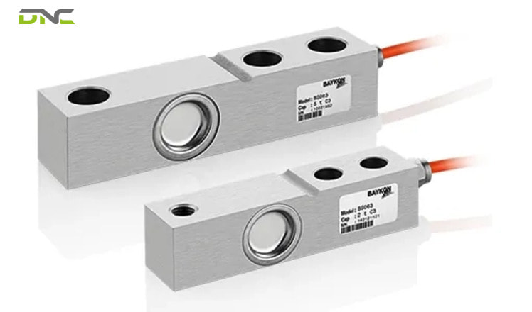
Digital and analog load cells both sense force with bonded strain gauges, and they differ in one architectural decision: where the analog-to-digital conversion happens. An analog load cell sends raw millivolt voltage down its cable to a summing junction box, and conversion occurs at the indicator. A digital load cell converts inside its own housing, corrects for its individual characteristics onboard, and transmits a number over a serial link such as RS-485. That single difference propagates into signal strength, noise immunity, sample rate, calibration labour, fault diagnosis, cabling, and vendor compatibility. For Malaysian factory engineers specifying a weighing system, the choice determines commissioning hours and diagnostic capability far more than it determines sensor accuracy.
Digital and Analog Load Cells Differ at One Point in the Signal Chain
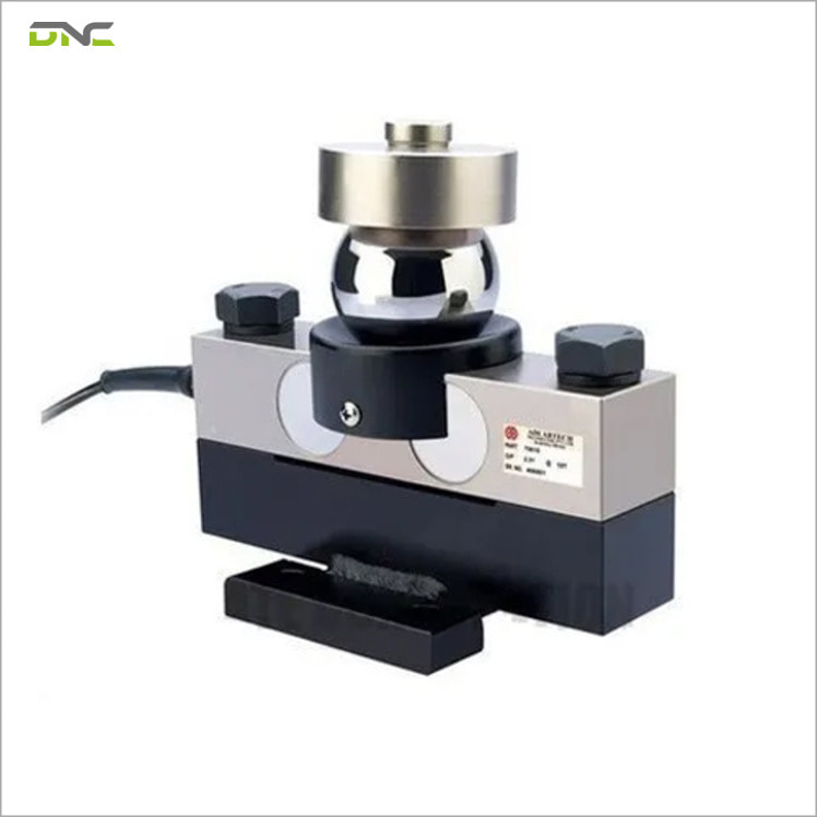
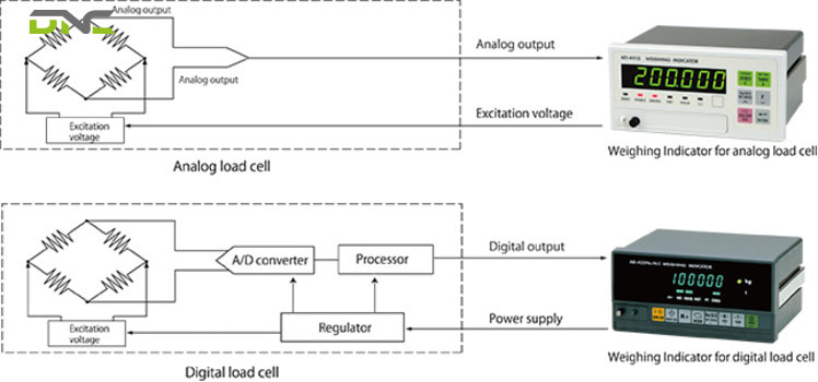
From a signal architecture point of view, digital and analog load cells differ in the physical location of the analog-to-digital converter. Both technologies start identically. Strain gauges bonded to a machined spring element change resistance under load, and a Wheatstone bridge turns that resistance imbalance into a differential voltage.
The divergence begins immediately after the bridge. An analog load cell outputs voltage, and that voltage travels the full cable run to a summing box and then to the terminal, where A/D conversion happens. A digital load cell performs A/D conversion using an internal converter, applies arithmetic correction for peculiarities in its own output, then sends a digital signal to the indicator.
The table below summarises the operational consequences of that architectural split.
| Characteristic | Analog Load Cell | Digital Load Cell |
| A/D conversion point | At the indicator or terminal | Inside the load cell housing |
| Transmitted signal | Raw voltage, around 0.03 V | Binary data at 2 V to 6 V |
| Output dependence | Proportional to excitation voltage | Numeric value, independent of excitation |
| Data per cell | One combined voltage after summing | Individual reading from every cell |
| Data rate | Continuous, real-time | Sampled bits, many times per second |
| Corner correction | Resistance trimming in the junction box | Applied digitally at the indicator |
| Fault isolation | Difficult across a summed signal | Per-cell diagnostics |
| Cross-vendor mixing | Cells and indicators freely combined | Same manufacturer recommended |
| Typical accuracy | 0.03% to 1% | Higher classes available |
Every row in that table traces back to the same root cause. Understanding the analog path first makes the digital advantages read as engineering consequences rather than marketing claims.
Digital and Analog Load Cells Differ at One Point in the Signal Chain
How an Analog Load Cell Moves Force Data to the Terminal
From a transmission point of view, unlike a digital cell, an analog load cell produces a low-voltage differential signal whose magnitude depends on the excitation voltage supplied by the indicator. Rated output is expressed in millivolts per volt, and the actual output is a simple product of that rating and the applied excitation.
A worked example fixes the relationship. A load cell rated at 2 mV/V, excited at 10 VDC and loaded to its rated capacity, outputs 20 mV. Drop the excitation to 8 VDC and the same load produces 16 mV. The sensor reports a ratio, not an absolute number, so excitation stability becomes part of the measurement accuracy.
That signal is small. System Scale puts analog transmission at around 0.03 volts against 2 to 6 volts for digital transmission, which leaves the analog line far more exposed to fluctuation and electrical noise. Radio frequency interference, electromagnetic fields from nearby drives, and temperature shift all act on the cable itself.
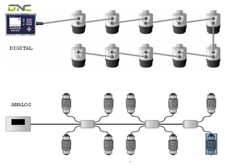
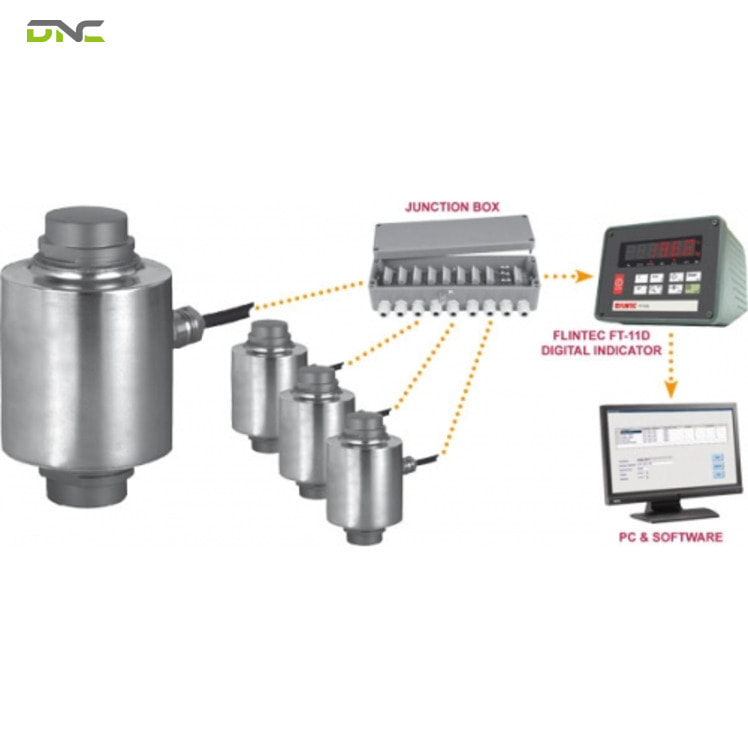
Multiple analog cells complicate the picture. Each cell routes its cable to an analog summing box where signals combine, and the combined result travels through a homerun cable to the terminal. Corner correction – compensating for off-centre load placement across cells – is performed by trimming resistance inside that junction box.
Analog architecture keeps its own advantages. Signal output is continuous and real time, hardware is straightforward to integrate, and cells and indicators from different manufacturers can be freely combined. Accuracy of properly installed analog cells reaches 0.03% to 1% depending on design and build quality, which covers the majority of industrial scales, hoppers, and batching systems in Malaysian plants.
How a Digital Load Cell Moves Force Data to the Indicator
From a data transmission point of view, a digital load cell outputs a number instead of a voltage, sent over serial communication such as RS-485 using a protocol such as Modbus-RTU. The measurement is already corrected and converted before it leaves the sensor body.
Binary data behaves differently on a cable than a 30 mV analog signal. Binary transmission resists radio frequency interference, electrical noise, and temperature change, so readings stay stable across long runs in electrically hostile environments – welding bays, VFD-dense panels, and motor rooms among them.
The payload also carries more than weight. A digital load cell can report overload records, manufacturer name, machine type, and serial number as digital values, none of which an analog cell can transmit. Modern digital systems extend that payload into diagnostics covering weighing errors, overloading, environmental conditions, network health, individual cell voltages, and enclosure integrity.
Sampling replaces continuity. A digital cell sends weight data in bits many times per second rather than as an unbroken voltage, and filtering runs at the cell before transmission. A continuous analog signal appears superior at first reading, and in practice several independently fluctuating analog signals summed together introduce more variability into the final weight than a filtered, consistent digital data stream does.
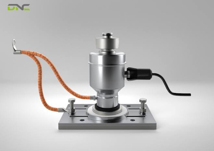
Construction often follows the electronics. Hermetically sealed housings with glass-to-metal connections make individual cells fully submersible, and daisy-chain topology replaces the analog junction box that constitutes a common failure point in wash-down environments.
How a Digital Load Cell Moves Force Data to the Indicator
Signal Strength, Signal Content, and Sample Rate Explain the Performance Gap
From a comparison point of view, digital and analog performance differences concentrate in three measurable characteristics: signal strength, signal content, and data sample rate. Vendors across the market converge on the same three axes, which makes them a reliable specification framework.
Signal Strength Determines Noise Tolerance Over Distance
Signal strength defines how well a reading survives the cable run. Digital load cells transmit at 2 V to 6 V because conversion happens before transmission, and they are no longer limited by the millivolt ceiling of a strain gauge bridge. Analog cells transmit at roughly 0.03 V, which degrades over distance and requires additional signal conditioning on long runs.
Cable length therefore functions as a specification input, not an installation detail. A control room 60 m (197 ft, 65.6 yd) from a tank farm imposes a different noise budget than a panel mounted 2 m (6.6 ft, 79 in) from the scale.
Signal Content Determines What the System Can Report
Signal content defines what information reaches the controller. An analog system transmits raw voltage and nothing else, so the terminal receives a weight and no context. A digital system transmits binary data from each individual cell, which is what makes per-cell diagnostics possible at all.
That distinction changes maintenance economics. A weighing platform that names its faulty corner eliminates the diagnostic sequence an analog platform demands.
Sample Rate Determines Behaviour Under Dynamic Load
Sample rate defines how the system handles motion. Analog cells deliver continuous real-time data suited to immediate feedback, and they carry noise along with it. Digital cells capture hundreds of measurements per second across hundreds of individual cells, which suits dynamic applications where force changes rapidly – in-motion checkweighing, robotic force feedback, and high-speed filling among them.
Filtering location matters as much as rate. Advanced filtering executed at the load cell delivers a steady value to the terminal, while an analog architecture pushes every fluctuation downstream for the indicator to resolve.
Signal Strength, Signal Content, and Sample Rate Explain the Performance Gap
Calibration Labour and Fault Diagnosis Separate the Two Architectures in Service
From a maintenance point of view, digital architecture cuts calibration labour at commissioning and shortens fault diagnosis when one cell in a group fails. Calibration effort and diagnosis time separate the two architectures in daily service, and neither difference appears on a datasheet.
Analog commissioning is hands-on. Summing several analog cells into one balanced platform requires adjusting output resistance in the junction box, and off-centre placement error correction for each cell is generally performed in that same box. Every adjustment is physical, sequential, and dependent on technician skill.
Digital commissioning shifts that work into software. Output resistance adjustment becomes unnecessary, and off-centre placement error is corrected digitally at the indicator, which reduces calibration work and labour compared with analog cells. Factory-programmed calibration extends the principle by carrying calibration data inside the cell itself.
Fault isolation follows the same logic. Detecting that one cell in an analog group is malfunctioning is difficult, because the summed signal hides the individual contribution. A digital indicator identifies a malfunctioning cell immediately, since each cell outputs its own signal and a silent cell is visibly absent from the network.
DNC’s engineers weigh this against downtime cost rather than capital cost. A four-cell platform scale under a filling line that stops production during fault-finding justifies digital diagnostics on availability grounds, even where analog accuracy would have been adequate.
Cable, Wiring, and Vendor Compatibility Constrain Retrofit Projects
From a retrofit point of view, digital load cells impose wiring and vendor constraints that analog systems do not. These constraints decide the true cost of converting an existing installation, and they are the most frequently missed line item in a weighing upgrade budget.
Existing analog cable cannot be reused. Analog load cell cables are not designed for serial data communication standards such as RS-485, so a digital conversion means pulling new cable. Digital cells use shielded twisted pair in a four-wire duplex arrangement, carrying data in one direction and DC power in the other.
Power delivery adds a second check. Digital load cells receive DC power in the 7 V to 10 V band, and long cable runs must be checked for voltage drop to confirm the specified voltage still arrives at the cell.
Vendor policy is the constraint with the longest tail. Analog load cells and indicators from different manufacturers can be freely combined, which keeps spares generic and procurement competitive. Digital specifications share many basic components while each manufacturer adds proprietary elements, and applied voltage varies by company, so cells and indicators should be sourced from the same manufacturer.
Procurement teams should read that as a lifecycle commitment. Specifying digital load cells on a 15-year asset ties the spares chain and the indicator replacement path to one supplier, which is a defensible decision when it is made deliberately at specification stage and an expensive surprise when it is discovered at the first failure.
Cable, Wiring, and Vendor Compatibility Constrain Retrofit Projects
Summary of the Architectural Differences So Far
Summary so far: four architectural differences between digital and analog load cells carry the specification decision, and each traces to the position of the A/D converter. Signal robustness comes first: analog transmits about 0.03 V (30 mV, 0.00003 kV) down the cable while digital transmits 2 V to 6 V of binary data immune to interference on the line. Data granularity comes second: analog delivers one summed voltage, digital delivers a reading plus diagnostics from every cell. Commissioning labour comes third: analog needs resistance trimming and corner correction inside the junction box, digital applies both digitally at the indicator. Wiring and vendor lock-in come fourth: digital needs new shielded twisted pair and a single-manufacturer cell-and-indicator pairing.
A “Digital Weighing System” Is Not Always a Digital Load Cell
From a specification-audit point of view, digital indicators get misread in weighing quotations as evidence of digital load cells, which they are not. All digital load cells form part of a digital weighing system, and not all digital weighing systems use digital load cells.
Hybrid architectures explain the confusion. Some systems retain analog load cells and convert the signal to digital later, inside the junction box. Those systems offer improvements over a fully analog setup, and they do not deliver the full benefits of true digital load cell technology, because the raw millivolt signal still travels the cable run from each cell and per-cell data never exists.
Three questions separate the two on a quotation. Ask where A/D conversion occurs, ask whether the system reports diagnostics for each individual cell, and ask which communication protocol runs between cell and indicator. A supplier quoting true digital cells answers with a location inside the cell, a per-cell diagnostic list, and a protocol name such as Modbus-RTU.
A “Digital Weighing System” Is Not Always a Digital Load Cell
Five Operational Variables Decide the Right Load Cell Architecture
From a selection point of view, digital or analog load cell architecture is decided by five operational variables, not a general preference for the newer technology. DNC’s engineers apply the same five variables whether the weighing point sits under a hopper, on a conveyor, or inside a palletising cell.
The selection variables are listed below in the order they change the outcome.
- Cell count per platform.Single-cell weighing points gain little from digital architecture, while four-cell and six-cell platforms gain corner correction and per-cell fault isolation.
- Cable run and electrical environment.Long runs near variable frequency drives, welding equipment, or high-power switchgear favour digital transmission at 2 V to 6 V.
- Downtime cost.Production lines where a weighing fault stops output justify per-cell diagnostics on availability grounds.
- Wash-down and ingress exposure.Hermetically sealed digital cells in daisy-chain topology remove the junction box, which is a recurring failure point in food and beverage plants.
- Spares and vendor policy.Facilities that require multi-vendor spares interchangeability keep analog architecture, since analog cells and indicators mix freely across manufacturers.
Analog remains the correct engineering answer in a large share of installations. Static tank weighing, batching systems, and general industrial scales in electrically quiet areas achieve 0.03% to 1% accuracy with straightforward integration and generic spares.
Digital earns its cost where data matters as much as weight. Automated manufacturing lines, robotic force feedback, laboratory-grade measurement, and any weighing point feeding quality records benefit from higher accuracy classes and from diagnostic content the analog signal cannot carry.
Specifying Load Cells Inside a Malaysian Automation Project
From an integration point of view, specifying digital or analog load cells inside a Malaysian automation project belongs at the control system design stage, not at the procurement stage. Signal type dictates panel design, cable schedule, indicator selection, and PLC interface, and each of those becomes expensive to change after the mechanical layout is frozen.
Weighing points rarely stand alone. A load cell fitted under a conveyor system inherits the vibration profile of the frame, and the filter setting, sample rate, and controller scan time must be specified together for in-motion weighing to hold tolerance. DNC’s engineering team treats the mounting structure, sensor, signal path, and controller as one deliverable during commissioning across a project base exceeding 1,000 installations.
Weight data also travels upward. Digital cells feeding a smart manufacturing layer through SCADA and IoT connectivity deliver overload history, cell health, and batch weights into the same reporting stream, which supports yield analysis and traceability records. That data path carries direct relevance under NIMP 2030, where Industry 4.0 incentives favour Malaysian manufacturers able to demonstrate connected, instrumented production.
Automation compounds the benefit. Weighing errors that trigger rework or giveaway on a manual line propagate into scheduling losses on an automated one, and error reduction in the 75% to 80% range across DNC-commissioned automation projects depends on measurement points that report their own condition.
If your facility is evaluating a new weighing system or converting an existing analog installation, DNC’s engineers can specify the architecture against your cell count, cable route, environment, and diagnostic requirements. Bring your line layout and downtime cost to the specification stage, and Get a Free Consultation before the panel drawings are released.
Specifying Load Cells Inside a Malaysian Automation Project
Frequently Asked Questions
What is the main difference between a digital and an analog load cell?
The main difference is where analog-to-digital conversion takes place. An analog load cell transmits raw voltage to an indicator that performs the conversion, while a digital load cell converts and corrects the signal inside its own housing and transmits a numeric value over a serial link such as RS-485.
Are digital load cells more accurate than analog load cells?
Digital load cells reach higher accuracy classes in service, largely because the signal is protected rather than because the sensing element is superior. Both types use strain gauges, and properly installed analog cells achieve 0.03% to 1% accuracy. Digital transmission removes noise, temperature drift, and interference from the cable run, which preserves that accuracy at the indicator.
Can I replace analog load cells with digital ones on an existing scale?
Replacing analog load cells with digital ones on an existing scale requires new cable and usually a new indicator. Analog load cell cables are not rated for serial data communication such as RS-485, so digital cells need shielded twisted pair in a four-wire duplex arrangement. Cost the conversion as a signal-path project rather than a sensor swap.
What are the vendor compatibility rules for digital load cells?
Vendor compatibility rules for digital load cells are stricter than the analog equivalent. Analog load cells and indicators from different manufacturers combine freely. Digital load cells should be paired with an indicator from the same manufacturer, because each company adds proprietary elements to the common specification and applied voltage varies between suppliers.
Why is my analog load cell signal only a few millivolts?
An analog load cell outputs a ratio of the excitation voltage, expressed in mV/V. A cell rated at 2 mV/V excited at 10 VDC produces 20 mV at rated capacity, and the same cell excited at 8 VDC produces 16 mV. Low output is normal, and it is the reason analog runs are sensitive to noise.
Does a digital indicator mean the system uses digital load cells?
A digital indicator alone proves nothing about the load cells. Some systems keep analog cells and convert the signal in the junction box, which improves on a fully analog setup without delivering per-cell data or diagnostics. Confirm the conversion point, the per-cell diagnostic list, and the communication protocol before accepting the quotation.
- 15 views
- 0 Comment
Recent Comments