


VFD Meaning, Wiring, Braking Resistor and Soft Starter
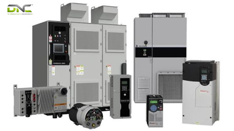
A VFD (variable frequency drive) is a motor controller that varies the frequency and voltage supplied to a three-phase AC motor, and motor speed follows that frequency. Inside the VFD, a rectifier, a DC bus capacitor and an IGBT inverter turn fixed line power into adjustable AC through pulse width modulation (PWM). Every VFD is a variable speed drive (VSD), but not every VSD qualifies. A braking resistor dissipates the energy a load returns to the DC bus, and a soft starter only ramps the start to full speed.
Five decisions shape a drive installation on a Malaysian factory line: VFD vs VSD naming, motor pairing, wiring, the braking resistor and the soft starter. Engineers specifying conveyor, pump and fan drives, including Siemens SINAMICS units supplied by DNC Automation, meet them in every project.
VFD Meaning: Variable Frequency Drive Defined
VFD meaning is variable frequency drive: an electronic motor controller that varies the frequency and voltage of the power it supplies to an AC motor. Motor speed follows that frequency. The synchronous speed in rpm equals 120 times the supply frequency in hertz divided by the number of poles, per one drive manufacturer’s selection guide.
A 4-pole motor therefore turns at 1,500 rpm on 50 Hz, 1,800 rpm on 60 Hz and 750 rpm when the drive outputs 25 Hz. Without a drive, the motor runs at the speed that its mains frequency and pole count fix. With a VFD between the supply and the motor, your production line gets a speed that follows the process instead of the grid.
The same device carries many labels. Vendors call it a frequency inverter, inverter, AC drive, frequency converter, adjustable speed drive or VSD, and the sections below show why those names overlap. A “VFD motor” is not a special machine either: it is an ordinary three-phase motor, usually an induction motor, that a VFD drives. DNC Automation supplies and commissions the Siemens SINAMICS frequency inverter range for Malaysian factories, with power ratings from 0.12 kW (120 W / 0.16 hp) to 630 kW (700 hp).
The adjustable output comes from three stages inside the drive, and the next section follows them in order.
VFD Working Principle: Rectifier, DC Bus and Inverter
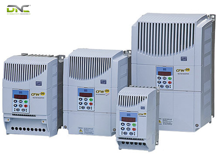
The VFD working principle has three stages: a rectifier converts AC line power to DC, a DC bus capacitor smooths and stores it, and an inverter switches it back into AC at the chosen frequency and voltage. The table lists the part and the job of each stage.
| Stage | Main part | Job |
| Rectifier | Diode bridge (six diodes in a standard low-voltage drive) | Converts three-phase AC to DC |
| DC bus | Capacitor | Smooths the ripple and holds the energy |
| Inverter | IGBT switches driven by PWM | Builds AC at the output frequency and voltage |
The inverter stage uses pulse width modulation. The switches turn the bus voltage on and off many times per second, and the pulse width sets the average output voltage. A carrier frequency of 2,000 Hz to 16,000 Hz is common in low-voltage drives, per the Wikipedia entry on variable-frequency drives. To hold the voltage-to-frequency ratio, a drive that halves the frequency also halves the output voltage.
Three control methods are common. V/Hz control holds a constant voltage-to-frequency ratio and suits pumps and fans. Vector control uses motor feedback to regulate speed and torque more precisely. Direct torque control targets cranes, crushers and conveyors, according to a drive manufacturer’s guide.
The DC bus is where the drive stores energy, so it is the attachment point for every accessory in this guide. Line-side parts clean what feeds the bus. A braking resistor takes surplus energy off it. Motor-side parts protect what leaves the inverter.
That layout is what a VFD is, and the broader label VSD covers drives that do not share it, which is the next question.
VFD Working Principle: Rectifier, DC Bus and Inverter
VFD vs VSD: Same Drive at Different Scope
VFD vs VSD is a question of scope: a VFD is a variable speed drive that changes speed by changing frequency, so every VFD is a VSD and not every VSD is a VFD. Most pages that compare the two state this subset rule. Several drive manufacturers’ guides instead state that VFD, VSD and AC drive name the same device.
Both positions are correct at different scopes. The subset rule covers every way of varying speed: a DC drive for a DC motor, an eddy-current coupling that changes the load speed while the AC motor keeps running at full speed, and mechanical or hydraulic variable-speed devices. The same-device position covers the case this guide addresses, a three-phase AC induction motor on a factory line, where the speed device is a VFD and VSD is another label for it.
One eddy-current vendor reports that its coupling beats a VFD on system efficiency above about 82 % of base speed, and recommends running the coupling at 80 % to 100 % of rated speed. That figure is a vendor claim for one technology. It is not a rule for AC drives.
The table sorts the VFD names by scope and motor type.
| Name | Scope | Motor type |
| VFD | Varies frequency and voltage | AC only |
| VSD | Any method of varying speed | AC or DC |
| AC drive, frequency converter, VVVF | Synonyms for VFD | AC only |
| Inverter | The DC-to-AC stage, also used for the whole drive | AC |
| Eddy-current drive | Varies coupling slip while the motor runs at full speed | AC motor with a coupling |
| DC drive | Varies the voltage at the motor armature | DC only |
A datasheet that says VSD for an AC induction motor means VFD. A datasheet that says VSD for a DC motor or a coupling does not.
The VFD inverter label resolves the same way. The inverter is the DC-to-AC stage inside the VFD, but the industry now calls any DC-to-AC converter an inverter, including solar and UPS equipment, per two vendor guides. A VFD inverter is therefore a VFD, and a solar inverter is not.
Whatever the label, plants buy a VFD for one shared reason: the energy a motor draws at part speed.
VFD Energy Saving: The Cube Law at Part Speed
VFD energy saving follows the affinity laws, which make the power of a centrifugal fan or pump fall with the cube of its speed. At 63 % speed the load draws 25 % of its full-speed power, per the Wikipedia entry on variable-frequency drives. A distributor’s guide gives 12.5 % power at 50 % speed. The table lists the arithmetic.
| Speed (% of full) | Power (% of full) | Basis |
| 100 | 100 | Reference |
| 80 | 51 | Cube of 0.80 (derived) |
| 63 | 25 | Wikipedia entry |
| 50 | 12.5 | Cube of 0.50 (distributor’s guide) |
Manufacturers quote VFD energy-bill savings from 20 % to 60 % on fans, pumps and chillers. Your saving depends on how many hours the load runs below full speed: a pump that runs at 95 % speed all day still draws 86 % of full power (0.95 cubed).
Conveyors and cranes follow a different logic. One drive manufacturer states that the primary reasons for drives on these machines are process optimisation and precise speed and position control, and that savings are unlikely to reach the 40 % it quotes for fans and pumps. On a conveyor system, the drive earns its place through ramp control: an S-curve ramp smooths acceleration and deceleration and reduces backlash, while abrupt starts and stops spill product or overload the mechanics.
A saving only materialises when the motor behind the drive suits it, which makes motor pairing the next check.
VFD Motor Pairing: Induction, Inverter-Duty and Slip
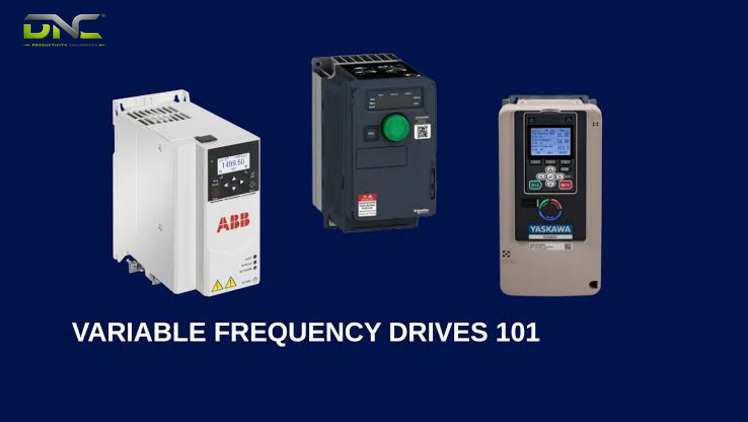
A VFD motor is most often a three-phase induction motor, because that type is the most economical match for a drive. Motors built for fixed-speed duty are often used. The voltage stresses a drive adds call for motors designed for inverter-fed duty, such as motors meeting Part 31 of NEMA Standard MG-1, per the same entry. Permanent-magnet and synchronous reluctance motors also run on drives.
Efficiency class alone does not settle the pairing. One drive manufacturer notes that replacing a direct-on-line motor rated IE1 to IE3 with an IE4 motor can raise the energy a fan or pump uses, because the IE4 motor runs at higher slip. A VFD goes with that upgrade to recover the saving.
A DC motor needs a DC drive. That drive is a VSD but not a VFD, because a DC motor has no supply frequency to vary.
A mismatch is not harmless. Incorrect setup, such as unmanaged harmonics or voltage spikes, can damage motor windings, while a correctly configured drive extends motor life, per a manufacturer FAQ. Specification starts at the motor nameplate: power, voltage, current and pole count. The drive then asks for the same nameplate data, plus the speed reference source, the on/off source and the braking control, as typical parameters.
Nameplate data goes into the drive parameters, but the conductors that carry the power are a separate job, and one manufacturer’s list of common mistakes puts improper wiring next to incorrect sizing, poor cooling and ignored harmonics.
VFD Motor Pairing: Induction, Inverter-Duty and Slip
VFD Wiring: Line, Motor, Braking and Control Terminals
VFD wiring has four terminal groups: line input from the supply, motor output, a braking resistor connection on drives that include a braking chopper, and control terminals for start, stop and speed reference. Terminal labels differ by model, so the drive manual governs each connection. The list below follows the order in which power flows.
- The line input feeds the rectifier. Many installations place a contactor on the three line conductors (L1, L2, L3) so that the drive powers up when the contactor closes. Line reactors and harmonic filters, where the supply needs them, sit in this group.
- The motor output leaves the inverter on three conductors. Cable length and shielding matter here, because the output is a train of fast pulses.
- The braking resistor connection links to the DC bus through the braking chopper. The next section explains when it is needed.
- The control terminals take a hardwired speed reference of 4 mA to 20 mA or 0 V to 10 V DC, or an internal 24 V DC supply with a potentiometer, and many drives add a network port for Modbus, Modbus/TCP or EtherNet/IP.
In a PLC-controlled line, the PLC writes the speed reference and the start command to the drive. The PLC is the automation controller and the VFD is the motor controller, per a manufacturer FAQ, a split that PLC, HMI and SCADA explains for the whole control layer. Remote control makes the drive ignore keypad speed commands, and local control makes it ignore the external signal. For Malaysian manufacturers working toward the Industry 4.0 goals of NIMP 2030, drive parameters and fault logs read over Modbus or EtherNet/IP become plant data instead of panel-door readouts.
The motor cable is where wiring turns into physics. Pulses reflect from the motor terminals back down the cable and produce overvoltages up to twice the DC bus voltage, or up to 3.1 times rated line voltage on long runs, per the same entry. For 460 V and 575 V systems with third-generation IGBTs, that entry gives about 50 m (150 ft) as the recommended maximum distance between drive and motor, while a distributor puts the concern at 30 m (100 ft) and above. Treat 30 m to 50 m (100 ft to 150 ft) as the range where output filters enter the specification, and read the figure in the manual of the model you buy. The listed fixes are a shorter cable, a lower carrier frequency, a dV/dt filter, an inverter-duty motor and an LCR sine-wave filter.
Bearing currents follow the same path. Carrier frequencies above 5 kHz are likely to damage bearings unless protective measures are taken: shielded symmetrical-geometry power cable, shaft grounding brushes or rings, insulated bearings and common-mode chokes. Incorrect grounding and wiring can cause malfunctions and damage the motor, according to a drive manufacturer’s guide, so commissioning checks the earth connections before the first start.
Of the four terminal groups, the braking connection is the only one that discards energy as heat instead of passing it to the motor, which is why it needs its own section.
VFD Braking Resistor: Where Regenerated Energy Goes
A VFD braking resistor dissipates the energy that returns to the DC bus when a load drives the motor faster than the drive commands, and it converts that energy to heat. The motor then acts as a generator and sends power back to the drive’s DC link. A braking chopper, an electronic switch connected to the DC link, controls how the power is dissipated as heat in a set of resistors, and cooling fans can keep the resistors from overheating, per the same reference.
Few loads send energy back to a VFD. Centrifugal pumps and fans are single-quadrant loads in most installations, and they return energy only when the drive slows them faster than their own losses do. Hoists, elevators and hilly conveyors are four-quadrant loads that overhaul the motor. The same reference lists conveyor belt drives that stop every few minutes, and cranes whose hoist stops and reverses often, among the uses of regenerative drives.
Four decisions settle the VFD braking design. The list below follows the order in which they come up.
- Confirm whether the load overhauls the motor, which means checking each stop, each descent and each slope on the line.
- Check that the drive includes a braking chopper, because the resistor connects through it. Manufacturers advise looking for braking choppers when the application is a crane or a lift.
- Take the resistance value from the VFD datasheet. A drive reseller states that the datasheet indicates it, so the drive model, not the motor alone, is the source.
- Choose between dynamic braking and a regenerative drive. Dynamic braking wastes the braking energy as heat. A regenerative drive returns it to the AC line at a relatively high capital cost, and it pays back only where the recovered energy is large against the extra cost and braking and starting are frequent. A manufacturer lists Active Front End technology as its answer for rapid, controlled braking on cranes, lifts and conveyor belts.
A VFD braking resistor adds heat to the panel, so enclosure ventilation belongs to the same decision. DNC recommends testing the stop under full load at commissioning, because braking energy appears only when the load drives the motor, and a loaded stop is the test that shows it.
VFD wiring, filters and braking all attach to the DC bus or to its two neighbouring sides, which the summary below sorts before the comparison with the soft starter.
Summary: VFD Accessories by Side of the DC Bus
A VFD accessory belongs to one of three sides of the DC bus: the line side, the DC side or the motor side. Line-side parts manage what the supply feeds in. DC-side parts handle energy that the load returns. Motor-side parts protect the cable, windings and bearings from the output pulses. Naming (VFD, VSD, inverter) does not change this layout, and part-speed operation changes the energy bill, not the wiring. The table assigns each accessory to its side.
| Side | Accessories | Problem handled |
| Line side | Contactor, line reactor, harmonic filter, Active Front End drive | Switching the drive on and off; harmonic distortion on the supply |
| DC side | Braking chopper with resistor; regenerative drive | Energy returned by an overhauling load |
| Motor side | Shielded cable, dV/dt filter, sine-wave filter, inverter-duty motor, shaft grounding | Reflected-wave overvoltage; bearing currents |
| Outside the bus | Soft starter, bypass starter | A start path that ramps the motor to full speed or bypasses the drive |
The soft starter sits outside this VFD map: it ramps the motor to full speed during startup and does not vary the speed afterwards.
VFD Accessories by Side of the DC Bus
VFD vs Soft Starter: Ramp Only or Speed Control
A VFD controls motor speed throughout the run, while a soft starter only provides a gentle ramp-up to full speed during startup. An across-the-line contactor applies full line voltage to the motor. A direct-on-line start draws up to eight times full-load current, per the same reference, and over 600 % of rated current, per a distributor’s guide, so the working range is roughly 6 to 8 times.
A VFD begins at low frequency and voltage and ramps both, which avoids that inrush. It also controls the ramp-down at stop. The table compares the three starting methods.
| Attribute | Direct-on-line contactor | Soft starter | VFD |
| Voltage at start | Full line voltage | Ramped | Ramped together with frequency |
| Speed after the start | Fixed by mains frequency and poles | Full speed | Adjustable throughout the run |
| Energy saving at part load | None | None | Cube law on fans and pumps |
| Braking energy | Not managed | Not managed | Resistor or regenerative path on the DC bus |
The decision rule follows from the table. DNC recommends a soft starter when the load runs at one speed and only the start needs softening, and a VFD when the process needs speed, torque, positioning or a braking path. Panels often combine both: a bypass starter scheme lets a pump keep running if the VFD fails, per an eddy-current vendor and a distributor. DNC Automation offers VFD and soft starter panels within its electrical and instrumentation service, next to MCC and PLC control panels, and the site lists site installation and commissioning alongside them.
Once the start method is chosen, the remaining question is which drive to specify.
VFD Selection and Siemens SINAMICS Range for Malaysian Factories
VFD selection for a Malaysian factory runs through six checks before any model number is written down. The list below follows the order in which the checks narrow the choice.
- Motor data: power in kW or hp, voltage, current and motor type.
- Load torque: constant torque for conveyors and crushers, variable torque for pumps and fans.
- Starting torque, overload capacity and the acceleration and deceleration the process needs.
- Environment: the enclosure IP rating and the cooling method.
- Communication: Modbus, Profibus or EtherNet/IP for the control system.
- Harmonics and protection: filters or an Active Front End drive, plus a braking chopper if the load overhauls the motor.
A Malaysian distributor’s listing for a 0.4 kW to 7.5 kW general-purpose drive shows how these checks surface on a datasheet: three-phase input of 200 V to 240 V or 380 V to 480 V, an IP20 enclosure, an output up to 600 Hz and Modbus RS-485. The voltage class and the enclosure rating belong on your specification from the first draft.
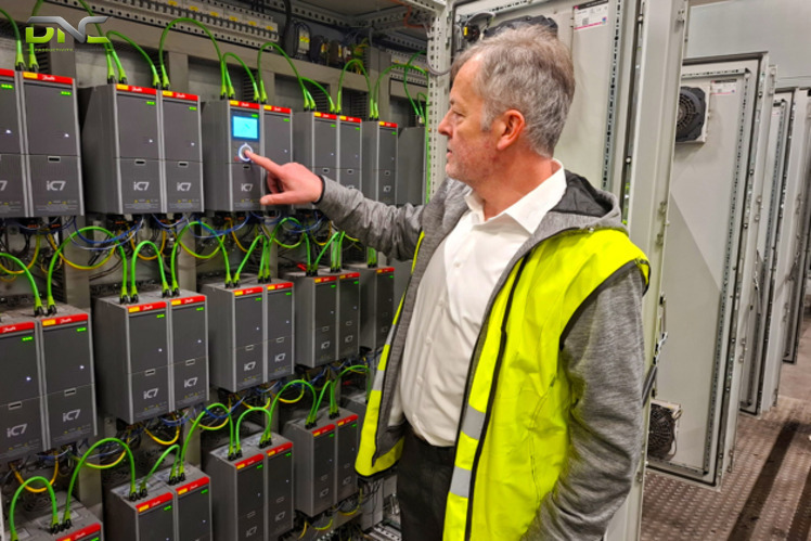
DNC’s frequency inverter page lists four Siemens SINAMICS series for pumps, fans, compressors, conveyors, mixers, mills and extruders. The table gives each series with its power range as published there.
| Series | Power range | Role |
| SINAMICS V20 | 0.12 kW to 30 kW (0.16 hp to 40 hp), 7 frame sizes | Compact drive for general motion sequences |
| SINAMICS G120X | 0.75 kW to 630 kW (1 hp to 700 hp) | Infrastructure drive for pumps, fans and compressors in water and wastewater, HVAC, irrigation and chillers |
| SINAMICS G120 | 0.37 kW to 250 kW (0.5 hp to 400 hp), 200 V, 400 V and 690 V variants | Modular vector drive with integrated Safe Torque Off, Safe Stop 1, Safety Limited Speed and Safe Brake Control |
| SINAMICS G120C | 0.55 kW to 132 kW (0.75 hp to 150 hp), 7 frame sizes | Compact vector drive for space-saving installation |
A turnkey drive installation joins these checks to the panel, the cabling, the braking path and the PLC integration, so one engineering team owns the stop behaviour as well as the start. A VFD sets speed by frequency, hangs its accessories on the DC bus, and earns its place on a conveyor line through control more than through energy.
Selection ends at commissioning, and the checks that keep the drive running follow it.
VFD Selection and Siemens SINAMICS Range for Malaysian Factories
VFD Maintenance: Cooling, Connections and Fault Checks
VFD maintenance covers four routine checks: cooling, connections, operating conditions and firmware. Heat sinks and fans need to stay clean and free of dust or debris, because overheating shortens drive life, per a drive manufacturer’s guide. Loose connections cause erratic behaviour or failure, so terminals are inspected on a schedule. Logging voltage, current and temperature shows a trend before it becomes a trip, and firmware updates keep the drive at its rated performance.
Fault logs shorten VFD diagnosis. Modern drives store each fault with a timestamp and the frequency, current and fault type recorded at that moment, and many let a technician upload and download parameters, so settings move between drives faster. The table lists the first check for each symptom that a manufacturer names and the side of the DC bus it belongs to.
| Symptom | First check | Side of the DC bus |
| Overheating | Blocked ventilation and cooling fans | Drive body |
| Unexpected shutdown | Overload conditions and faults in the motor wiring | Motor side |
| Voltage fluctuation | Line reactor or filter on the supply | Line side |
| Erratic behaviour | Loose connections and grounding | Line and motor sides |
Four VFD questions recur once a drive is in service, and the FAQ answers them in turn.
Frequently Asked Questions About VFDs
Frequently asked questions about VFD wiring, braking resistor and soft starter choices come up in most drive specifications, and each answer below repeats the rule from the section above. The first answer concerns the motor, the one component that every earlier section protects.
Can a VFD damage a motor?
A VFD damages a motor when it is set up wrongly: unmanaged harmonics and voltage spikes stress the windings, and long cables without filters raise the voltage stress further. A correctly configured drive extends motor life, per a manufacturer FAQ. Inverter-duty motors and output filters can reduce the stress.
When is a braking resistor needed on a VFD?
A braking resistor is needed on a VFD only when the load drives the motor faster than the drive commands, as hoists, elevators and hilly conveyors do. Centrifugal pumps and fans are single-quadrant loads in most installations, so most of them run without one.
What does a VFD do that a soft starter does not?
A VFD controls motor speed throughout the run and starts the motor from low frequency and voltage, while a soft starter ramps the start and then leaves the motor at full speed. A soft starter stays the better fit when the load runs at one speed and only the start needs softening.
Does a VFD need a PLC?
A VFD does not need a PLC, because most drives run from the built-in keypad or from hardwired terminals. A PLC adds automatic speed references over a network such as Modbus or EtherNet/IP, and in PLC-controlled systems the PLC commands the drive.
- 2 views
- 0 Comment
Recent Comments