


Control Panel for Pump: Components, Starters and Logic
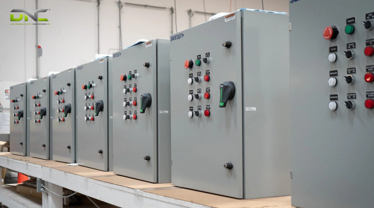
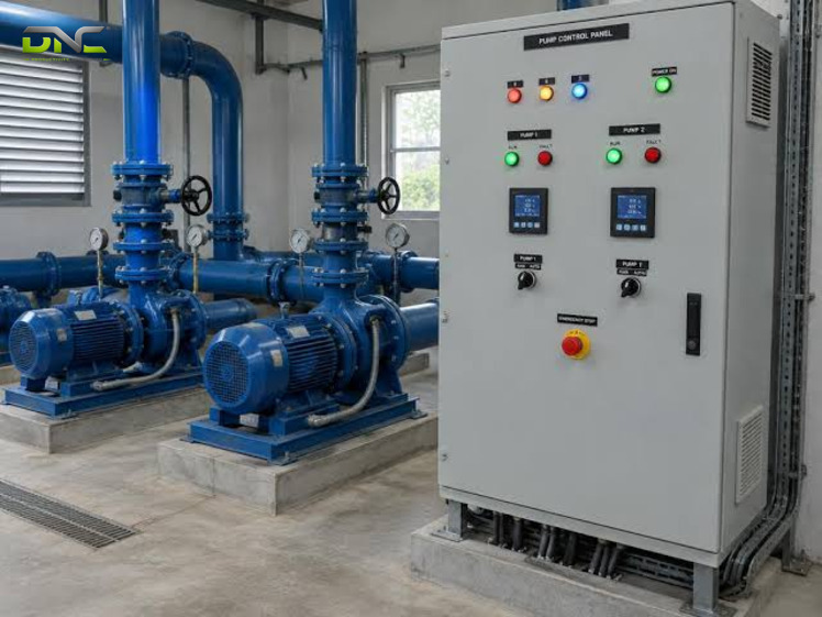
A pump control panel is an electrical enclosure that starts, stops and protects one or more pump motors from a level, pressure or flow signal. Inside sit a motor starter, a contactor, overload protection, a selector switch and indicator lamps, and in larger panels a soft starter or a variable frequency drive (VFD). The panel runs three command layers in a fixed order: protection first, the operator second, the process signal last.
That order explains every component and every fault. This guide covers four starting methods, float and pressure inputs, duplex pump logic, the nameplate data a water pump control panel needs and a fault-finding sequence for a pump that will not start. It suits plant engineers in Malaysia who specify or maintain pumping duty.
What a Pump Control Panel Does: Switch, Protect and Decide
A pump control panel does three jobs: it switches motor power, it protects the pump and motor, and it decides when the pump runs. In pump work, “control panel” means an electrical enclosure, not the Windows settings screen. The same device appears under other names: control panel for pump duty, pump starter panel, pump controller, water pump control panel.
A US panel builder describes the split the same way. Power components control the motor, sensors protect the pump and pilot devices give the operator control. A UK pump-filter maker adds the reason for the third job: the panel controls pump performance as depth, flow rate and power fluctuations vary. One pump maker’s range promises “effective protection and reliable control of all electric pumps”.
Small pumps such as sump pumps often ship with a pre-packaged control, while application-specific pump control panels are built to customer requirements, per the same builder. Each job maps to different hardware. Switching is a contactor and starter. Protection is an overload device, a voltage monitor and a level cut-out. Deciding is a float, electrode or pressure sensor plus the logic that reads it.
The pump control panel is the only place where all three meet. Each job maps to named components, listed next.
Pump Control Panel Components: From Incomer to Pilot Light
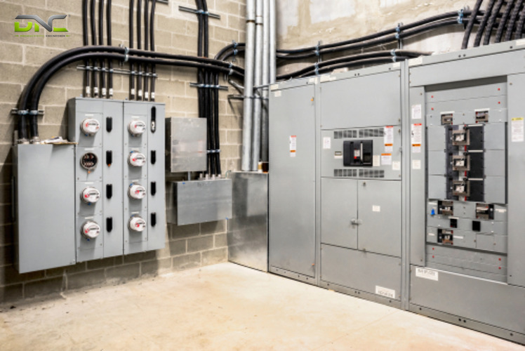
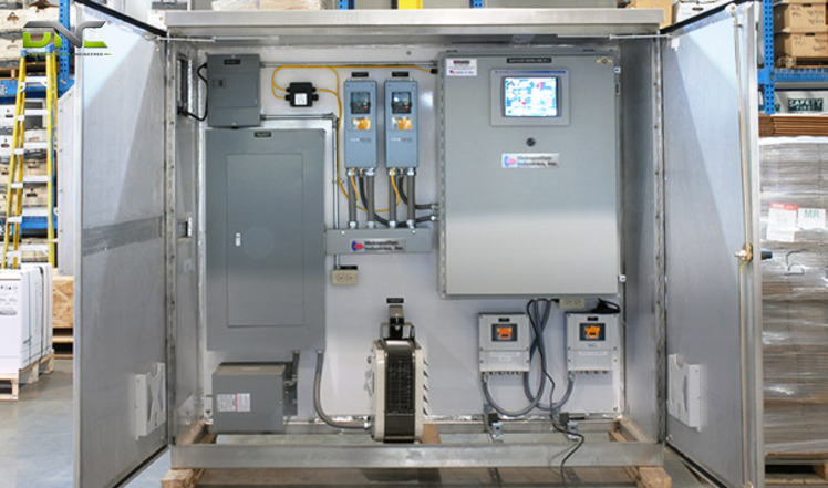
Pump control panel components fall into power parts, protection parts and signal parts, wired in order from the incoming isolator to the pilot lamps. The table lists the parts that one pump maker fits to its standard one-pump and two-pump panels, with the job of each.
| Part | Job in the pump control panel | Layer |
| Incoming isolator | Disconnects the whole panel from supply | Operator |
| Breaker (MCB or MCCB) per pump | Clears short circuits on that pump feeder | Protection |
| Contactor | Switches motor current; a contactor usually handles loads above 15 A (Wikipedia) | Power |
| Overload relay | Opens the starting circuit when motor current stays too high | Protection |
| Voltage relay | Guards against over and under voltage, phase sequence, asymmetry and phase failure | Protection |
| Auto-Off-Hand selector | Chooses automatic, stopped or manual running | Operator |
| Level electrodes, float or pressure switch | Tell the panel when to start and stop | Process |
| On and Trip indicators | Show running and tripped state | Operator |
| Ammeter, voltmeter, hour meter, multi-function monitor | Show current, voltage, running hours and power factor | Monitoring |
| Surge protection device | Limits damage from indirect surges; a lightning variant suits buildings with lightning protection | Protection |
Pump Control Panel Components: From Incomer to Pilot Light
Build quality decides how fast a pump control panel goes into service. One pump maker supplies panels pre-wired, with terminals for control accessories and for incoming and outgoing power, plus a wiring diagram. Its mild steel enclosure carries a baked powder epoxy finish and an ingress protection rating of IP54 or higher.
Larger panels add communication. A UK supplier lists remote monitoring and data logging, and a drive-based panel can pass pump status to a building management system over Modbus or Ethernet. DNC Automation lists VFD and soft starter panels and MCC and motor control for plants where pump starters sit inside a wider motor line-up. The parts above serve three different masters, and the next section ranks them.
Three Layers of Command: Protection, Operator and Process Signal
A pump control panel ranks three command layers in a fixed order of authority: protection first, operator second, process signal last. Protection stops the pump in every selector position. The operator layer overrides the process signal. The process signal acts only when the selector sits in Auto.
The protection layer of a pump control panel wins because of how the overload relay is wired. Per Wikipedia’s entry on motor controllers, the relay carries a normally closed contact that opens the starting circuit when the motor draws too much current for an extended time. That contact sits in the starting circuit of the contactor, which is why the protection layer wins over the selector in standard starter wiring. The same entry describes bimetallic and eutectic-alloy relays, and electronic relays that model winding heat from the measured current.
The operator layer comes next. A US panel builder lists a main disconnect and an Off-On or Manual-Off-Auto selector, and one pump maker fits Auto-Off-Hand selectors to its panels. Off keeps the pump stopped whatever a float reports. Hand runs it without the sensor, while the protection layer still trips it.
| Layer | Typical devices | Acts when | Overrides |
| Protection | Overload contact, voltage relay, level cut-out | A fault condition appears | Everything below it |
| Operator | Disconnect, Auto-Off-Hand selector, stop button | A person selects a state | The process signal |
| Process signal | Float, electrode, pressure switch, flow sensor | The selector sits in Auto | Nothing |
Restart behaviour belongs to the same table. A starter’s no-volt release (the TONVR protection in the Wikipedia entry) keeps a stopped motor from restarting by itself when supply returns, until someone presses start. An Auto circuit is wired to restart on demand, so the pump control panel design states which behaviour applies to each pump.
None of the five pump panel pages in the Malaysian search results for these keywords ranks the layers. They list parts. DNC’s engineers read a panel drawing by layer first and by part second. Once the layers are clear, the starter under the protection layer comes from the motor nameplate.
Three Layers of Command: Protection, Operator and Process Signal
Starting Method in a Pump Control Panel: DOL, Star-Delta, Soft Starter and VFD
The starting method in a pump control panel follows the motor nameplate: direct-on-line, star-delta, soft starter or VFD. One pump maker states that motor manufacturers usually specify the starting method and voltage on the motor nameplate, and it sorts its standard panels by that field. The table compares the four methods as the sources describe them.
| Method | How the panel starts the motor | What the panel adds | Pump benefit stated by sources |
| Direct-on-line (DOL) | Full voltage through one contactor | Contactor and overload device | Suits small fixed-speed pumps (US panel builder) |
| Star-delta | Star-connected winding first, then delta | Three contactors, timer, overload device | Winding current in star is 58 % (1/√3) of line current; change to delta at about 80 % of full-load speed (Wikipedia) |
| Soft starter | Voltage ramps up gradually | Line and bypass contactors | Lower starting current; less water hammer and check valve slamming (pump maker) |
| VFD | Frequency and voltage follow demand | Drive, cooling fans, emergency stop | Speed follows pressure or flow; savings suit systems with less than 50 % static head (pump maker) |
The same pump maker turns this into a naming code. Its panel 1PDS304 means one pump, DOL start, standard specification, three-phase 4 kW (5.4 hp / 4,000 W). The letters M, D, Y, S and V give manual, DOL, star-delta, soft starter and VFD. A code like this lets a buyer read the starting method straight off the panel label.
Size and speed control cut the choice further. A US panel builder uses an across-the-line starter for small fixed-speed pumps, a solid-state soft starter for large fixed-speed pumps to prevent water hammer, and a VFD where pressure or flow must be held. Soft starters need few adjustments compared with VFDs, according to Wikipedia. DNC supplies the Siemens SINAMICS frequency inverter range for the drive-based variant.
Whichever starter sits in the pump control panel, it still needs a signal that says when to run. That signal comes from the panel inputs.
Pump Panel Inputs: Float, Electrode, Pressure and Flow Signals
Pump panel inputs tell the control panel when to start: float, electrode, pressure and flow signals each give a different on-off logic. A US panel builder names the set: level sensors for control and dry-run protection, flow sensors to verify the pump moves fluid, pressure sensors for control and speed, temperature sensors for the motor. The table sorts them by what the panel receives.
| Input | What it detects | What the panel does with it |
| Float switch | Liquid level at a fixed height | Starts on one level, stops on another |
| Two-stage float | A second, higher level | Raises an alarm or cuts the inflow if the pump has failed or its discharge is blocked |
| Level electrodes | Low water in a tank or well | Cuts out the pump to prevent dry running |
| Pressure switch | Pressure at the contact setpoint | Closes or opens a contact on rising or falling pressure |
| Pressure transducer | Pressure as a continuous signal | Feeds a drive or controller that holds a setpoint |
| Flow sensor | Fluid moving past a point | Confirms the pump moves liquid |
Switch-type inputs to a pump control panel carry a gap between the start point and the stop point. Wikipedia’s float switch entry states that a float switch can include substantial hysteresis, which “minimizes the on-off cycling” of the pump, and its pressure switch entry describes the same deadband around the setpoint, adjustable on some types. The deadband sets the length of each pump cycle. A narrow gap means more starts per hour, and each start draws the motor’s starting current.
Electronic pressure switches use a transducer for better repeatability than a mechanical switch, per the same reference. A pump control panel built around a programmable logic controller reads transducers directly, and DNC’s programmable logic controller range covers that case.
These inputs, the three layers and the starter fix most of the panel before any wire is pulled, so the next section collects them.
Summary: What Sets a Pump Control Panel Before Wiring Starts
Five decisions fix a pump control panel before wiring starts: the layer order, the starter, the input, the pump count and the enclosure. The layer order is constant. Protection beats the operator, and the operator beats the process signal. The nameplate fixes the starter, the duty fixes the input, and the number of pumps fixes the logic. The table maps each decision to the section that covers it, and the order of the rows is the order of the work, because a late change to an early row forces a redraw of the panel.
| Decision | Fixed by | Where covered |
| Layer order | Always the same: protection, operator, process | Three layers section |
| Starter type | Motor nameplate and pump size | Starting method section |
| Input type | Duty: fill, drain or boost | Inputs and duty sections |
| Pump count and logic | Standby need and run-time balance | Duplex section |
| Enclosure and supply | Site, voltage, phase | Specification section |
The first three decisions fit one pump. The duty decides the next one, and the same panel family can run in opposite directions.
What Sets a Pump Control Panel Before Wiring Starts
Booster Duty Versus Sump Duty: Why Control Direction Differs
Booster duty and sump duty give a pump control panel opposite control directions: a booster starts when pressure falls, a sump pump starts when level rises. Wikipedia’s pressure switch entry lists a household well pump that switches on when water leaves the pressure tank. Its float switch entry describes a sump pump that starts on a rising level and runs until the level has fallen substantially.
A third direction exists for a pump control panel. A transfer pump that fills a tank starts when the float reaches a low level and stops at a higher one, per the same float switch entry. Level is the input in both the sump and the tank, yet the start logic is reversed. The table lists the three directions.
| Duty | Starts on | Stops on | Protection that matters most |
| Fill (transfer to a tank) | Falling tank level | Rising tank level | Dry-run cut-out on the source |
| Drain (sump, lift station) | Rising sump level | Fallen sump level | High-level alarm if the pump fails |
| Boost (pressure set) | Falling pressure | Rising pressure | Dry-run and overload |
Wastewater panels show the drain case. A pump supplier’s lift station page says the panel controls pumps based on liquid level sensors, and logs run times, events and alarms. A UK supplier lists wastewater lift stations and household water supply as separate applications for the same panel family. A control panel for pump duty therefore needs the duty written on the order, not only the motor size.
DNC’s reading is that a swapped input logic fails in a predictable way. A drain panel wired as a fill panel runs while the sump is empty and stays off while it floods. The high-level stage of a two-stage float then becomes the only protection left. Duty also decides how many pumps share the logic, which is the next question.
Duplex and Multi-Pump Logic: Alternation, Standby and Changeover
Duplex and multi-pump logic in a pump control panel decides which pump runs, in what order and what happens when one fails. A UK supplier lists the configurations as simplex (one pump), duplex (two), triplex (three) and quad (four). A US panel builder names the matching logic as duty-standby and lead-lag.
A Chinese panel supplier’s dual-pump page lists the modes in plain terms. In alternate mode, pump A leads one cycle and pump B leads the next, which balances running time and reduces wear. In main-standby mode, the second pump starts when the first fails or cannot meet the flow. In simultaneous mode, both run together. The table adds the trigger for each mode.
| Mode | What the panel does | Trigger |
| Alternate | Swaps the lead pump every cycle | End of each cycle |
| Duty-standby (main-standby) | Starts the second pump in place of the first | Fault on the duty pump |
| Lead-lag | Adds the lag pump to the lead pump | Demand above the lead pump’s capacity |
| Simultaneous | Runs both pumps together | Start signal |
| Trip changeover | Transfers duty after an overload trip | Protection layer |
Component sets decide whether the logic holds. One pump maker’s two-pump panels carry paired component sets, a changeover for auto cycle and auto trip changeover when specified, and independent Auto-Off-Hand selectors when each pump must run alone. Each pump then has its own contactor and overload device, so a trip on one pump leaves the other starter live.
Standby only exists when a trip transfers duty. Alternation, by contrast, acts on a cycle and does nothing for a failed pump. A pump control panel for critical duty therefore states both rules. A duplex panel doubles the nameplate data, so specification comes next.
Duplex and Multi-Pump Logic: Alternation, Standby and Changeover
Water Pump Control Panel Specification: Nameplate, Supply and Enclosure
A water pump control panel specification starts from the motor nameplate: power, voltage, phase and starting method. A Chinese panel supplier’s order form adds the rest. The table lists nine data fields and the panel part each field fixes.
| Data field | What it fixes in the panel |
| Number of pumps | Simplex or duplex logic, paired components |
| Motor power and current | Contactor, breaker and overload relay ratings |
| Voltage and phase | Single-phase or three-phase build |
| Starting method | DOL, star-delta, soft starter or VFD |
| Control mode | Manual, automatic or both |
| Signal type | Float, pressure switch, level controller or external signal |
| Application | Water supply, drainage, sewage, irrigation or process |
| Indoor or outdoor | Enclosure rating and finish |
| Special protection and alarms | Voltage monitor, surge protection, alarm contacts |
Malaysian supply narrows the choice. A Malaysian pump supplier lists single-phase controllers for 0.75 to 1.5 kW (1 to 2 hp / 750 to 1,500 W) at 240 V and 50 Hz, and three-phase controllers for 1.5 to 15 kW (2 to 20 hp / 1,500 to 15,000 W) at 415 V and 50 Hz. One pump maker’s standard range covers single-phase 0.37 to 1.5 kW (0.5 to 2 hp) and three-phase 1.1 to 45 kW (1.5 to 60 hp), and the same page quotes standard panels up to 90 kW (121 hp / 90,000 W). Your motor nameplate should sit inside one of these bands before a catalogue panel is considered.
The enclosure closes the specification. The ingress protection code follows IEC 60529, according to Wikipedia, and one pump maker sets IP54 or higher for its mild steel wall-mounted panels with a lockable door. The same maker fits Schneider components as standard and offers Lovato, Siemens or ABB on request. A Chinese supplier offers a branded-component version for buyers who want branded components with local replacement. The panel on the wall still fails now and then, and the three layers give the order for finding why.
Fault Finding: A Pump That Will Not Start
Fault finding on a pump control panel that will not start follows the three layers from the operator to protection to the process signal. The order costs the least time: each check is quicker than the one after it. The steps below assume a panel with On and Trip indicators and a voltage relay.
- Read the selector. Auto-Off-Hand on Off keeps the pump stopped whatever the sensors report.
- Read the Trip lamp. A lit lamp means the overload device or another protection device has opened the starting circuit.
- Read the voltage relay. A phase failure, a phase sequence fault or a voltage outside the monitor band keeps the pump out.
- Read the process signal. A float hanging at the wrong level, or a pressure switch set above the working pressure, makes the panel see no demand.
- Read the starter. A contactor that does not pull in with a live coil points to the contactor itself.
Reset an overload on a pump control panel only after finding the cause. A thermal overload trips when the motor draws too much current for an extended time, per Wikipedia, so a jammed impeller, a low supply voltage or a blocked discharge all show up as the same trip. Repeated resets hide the cause and heat the winding.
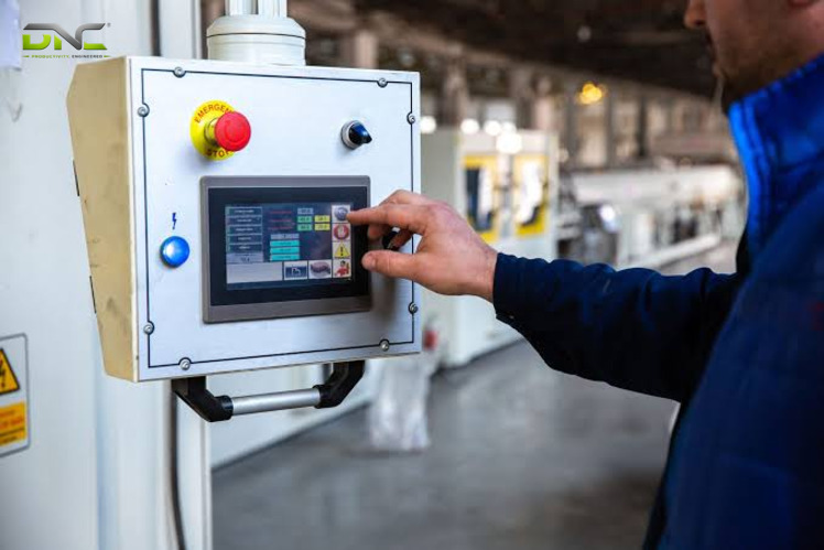
A panel on Auto can restart a pump on its own once the cause clears. A pump control panel for plants with several pumps therefore benefits from On and Trip lamps on the door and a run-hour meter. Plants that want these read remotely add a PLC layer, and that is where DNC Automation’s drive and PLC lines enter.
Fault Finding: A Pump That Will Not Start
DNC Pump Control Panel Support for Malaysian Plants
DNC Automation supports pump control panel projects in Malaysia through its drive, soft starter, motor control and PLC lines. The company lists VFD and soft starter panels, MCC and motor control, and programmable logic controller systems as separate categories, and its smart manufacturing range uses Siemens drives. Water treatment and energy are among the industries DNC serves.
A pump panel project follows the order of this guide. DNC’s engineers start from the motor nameplate, then fix the starter, the input logic and the pump count, and last the enclosure. The firm has 35+ engineers and ISO 9001:2015 certification. For your facility, the useful first document is the pump schedule: motor power, voltage, phase and duty for every pump.
The schedule then points to a panel family. A fixed-speed duplex booster maps to a DOL or soft starter panel. A booster whose demand varies maps to a drive panel. A plant with many pump motors maps to an MCC with one starter feeder per motor, and the starter type follows from each motor. A pump control panel for one pump and an MCC for forty pumps share the same three layers.
To specify a pump control panel for your plant, speak with a DNC engineer.
Frequently Asked Questions About Pump Control Panels
Five questions come up most often about a pump control panel in Malaysian plants: definition, selector, drive, pump count and enclosure rating. The answers follow the three-layer order used in this guide.
What is a pump control panel?
A pump control panel is an electrical enclosure that starts, stops and protects pump motors. It holds a starter, overload protection, a selector and indicators, and it reads a level, pressure or flow signal to decide when the pump runs.
What does the Auto-Off-Hand selector do on a pump control panel?
The Auto-Off-Hand selector on a pump control panel sets who controls the pump: the sensor in Auto, nobody in Off, and the operator in Hand. The overload device still trips the pump in Hand, because protection ranks above the operator.
Does a control panel for pump duty need a VFD?
A control panel for pump duty needs no VFD when the pump runs at fixed speed. A DOL or soft starter panel covers that case, and a VFD enters when pressure or flow must follow demand. One pump maker reports the clearest drive savings in systems with less than 50 % static head.
Does one control panel run two pumps?
One control panel runs two pumps when it is a duplex pump control panel built for that duty. The panel drives both pumps from one enclosure in alternate, main-standby or simultaneous mode. Each pump keeps its own contactor and overload device when the panel carries paired component sets.
Which enclosure rating does a water pump control panel need?
One pump maker’s standard water pump control panel range specifies IP54 or higher, with a hinged lockable door. IEC 60529 defines the IP code, so the rating is set by the site and the mounting position.
- 0 views
- 0 Comment
Recent Comments