


How to Choose Load Cell Capacity: Formula & Sizing Guide
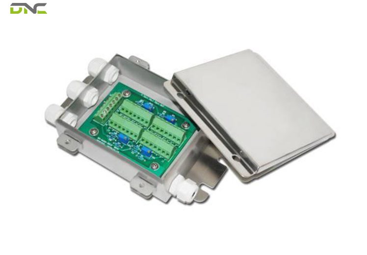
Load cell capacity is the rated load a cell is built to measure, and choosing it wrongly fails in two opposite directions. Specify it too low and impact, side thrust or an unbalanced load drives the cell past its rating until it deforms. Specify it too high and the readings lose resolution, most severely at the light end of the range where small weight changes stop registering. Correct load cell capacity comes from four weights added together – the product, the structure carrying it, the forces created by motion, and the forces arriving off-axis – then multiplied by a margin matched to the duty. This guide works through each weight, the sizing formula, how capacity divides across a multi-cell platform, how far to oversize before resolution suffers, and the conditions inside Malaysian plants that change the answer. It is written for plant, packaging and process engineers specifying a weighing system.
Rated Capacity Is a Rating, Not an Allowance
Load cell capacity is the rated load, also called full scale. It states the load the sensor measures and holds its calibration against. Every metrological figure on the data sheet is expressed relative to it: combined error as a percentage of full scale, the effect of temperature on zero and on full scale, the minimum weight increment the cell resolves. Change the capacity and every one of those figures changes with it.
Contrary to a common misconception, that rating is not an allowance – not a ceiling you may work up to with anything below it equally safe. Both halves of that reading fail in practice. Capacity is the value the cell was calibrated at, which makes it the denominator of the accuracy specification rather than a limit line. Reading it as a ceiling produces the two errors this guide exists to prevent: working too close to the rating in one direction, and buying rating you will never load in the other.
Capacity is therefore a two-sided decision rather than a safety decision. An undersized cell risks mechanical failure and the safety hazard that follows. An oversized cell survives everything and reports poorly, because resolution is a fraction of full scale, and a larger full scale makes every division coarser. Readings suffer most in the lower part of the range – exactly where a hopper sits before dosing starts, and where a checkweigher does its work.
Load cells also carry an ultimate overload rating separate from the rated capacity, describing the point of destruction rather than the point of accurate measurement. The rating exists to tell you what a fork truck accident might survive; it is not headroom you can specify against. Between the working load and that ultimate limit sits the margin – the subject of most of this guide.
For the geometry and sensing technology behind these ratings, see Load Cell Types Explained. This guide stays on capacity. That margin gets applied to a total, and the total is built from four separate weights.
Four Weights Decide the Number
The load a cell actually sees is the sum of four contributions, and only the first is the material you set out to weigh. Competitor selection guides tend to list the first two and mention the rest in passing. In practice the third and fourth are what shorten cell life.
Net Product Weight
The material being measured at its maximum – the full silo, the full drum, the heaviest carton the line will run. Take the maximum the process allows, not the nominal recipe, because the cell has to survive the overfill as well as the target.
Tare Weight, or Dead Load
The structure that permanently rests on the cells: the tank, hopper, platform, frame, agitator, piping stubs, insulation. Group Four Transducers separate this as the “dead load” against the “live load” of the material, and the distinction is worth keeping because dead load never leaves. It consumes capacity permanently, and on lightweight products it frequently exceeds the material weight several times over.
Dynamic and Impact Forces
Loading is rarely gentle. Galoce puts the typical dynamic addition at 20–50% above the static figure for impact forces created during loading. Where material free-falls into a hopper or a pallet lands on a platform, the instantaneous force climbs well beyond that – see the shock figures in the mistakes section below.
Parasitic Forces
Laumas defines these as the forces arriving from directions the cell was not designed for: impact, vibration, excess load on one side, forces introduced during material loading and unloading, acting from the side, from underneath or from another axis entirely. They damage the cell if its capacity is too low, and they corrupt the measurement even when they do not.
Their cost is measurable. Only when load arrives on the design axis does a cell deliver its full rating: ignoring side loads reduces effective capacity by 20–30% according to Galoce’s selection guidance – a cell rated 1,000 kg behaving like a 700–800 kg cell because the load never arrives straight down.
| Weight | What it is | Why it is missed |
| Net product | Maximum material measured | Nominal recipe used instead of maximum |
| Tare / dead load | Tank, hopper, platform, frame, fittings | Assumed small; often larger than the product |
| Dynamic / impact | Force created during loading | Treated as a rounding allowance |
| Parasitic / off-axis | Side thrust, vibration, unbalanced load | Not a weight at all in most guides |
All four feed a single equation.\\
Four Weights Decide the Number
The Capacity Formula, Worked Twice
Minimum load cell capacity = (net weight + tare weight) × dynamic factor × safety factor. The two multipliers do different jobs: the dynamic factor covers force the process creates, the safety factor covers what nobody predicted.
Worked example – tank weighing
Galoce’s published example: a 1,000 kg tank of material sitting on a 200 kg hopper, with a 1.3 impact factor and a 1.5 safety factor.
(1,000 kg + 200 kg) × 1.3 × 1.5 = 2,340 kg (5,159 lbf / 2.34 tonnes)
→ specify a 2,500 kg or 3,000 kg cell
The result is rounded up to a standard rating, not held at the calculated figure – 2,340 kg cells are not a catalogue item, and rounding down to 2,000 kg would put the working load above the rating.
Worked example – bagged product on a filling and palletising line
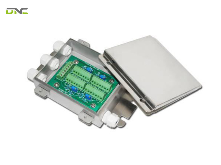
The same arithmetic applied to end-of-line packaging, where the structure dominates. A weigh hopper of 180 kg carrying a maximum 50 kg bag charge, fed by a screw that drops material rather than metering it gently, on a line that also sees a bag-clamp arm push against the frame:
(50 kg + 180 kg) × 1.3 dynamic × 1.5 safety = 448.5 kg (989 lbf)
→ specify a 500 kg cell
Note what the arithmetic exposes: the product is 22% of the load and the structure is 78%. Choosing capacity from the bag weight alone would have specified a cell roughly ten times too small.
The calculator
The specification comes down to five inputs, which is why it belongs in a calculator rather than a paragraph:
| Input | Example | Note |
| Net weight (max) | 50 kg | Process maximum, not nominal |
| Tare / dead load | 180 kg | Everything permanently on the cells |
| Dynamic factor | 1.3 | 1.2–1.5 for loading impact |
| Safety margin | 1.5 | Set by duty – see the margin ladder |
| Number of cells | 4 | Determines the per-cell figure |
Output: total required capacity ÷ number of cells → minimum capacity per cell → next standard rating up.
None of the four ranking selection guides offers this calculation as a tool, and it is the step engineers actually need to repeat.
The five inputs answer for a single cell. A tank, hopper or platform rarely rests on one.
Worked example – bagged product on a filling and palletising line
Dividing Capacity Across a Multi-Cell System
A tank, hopper or platform on several cells needs the total requirement divided by the cell count – and then protected against the assumption that the division is even. This is the step most selection guides skip entirely, despite multi-cell being the standard arrangement for anything larger than a bench scale.
The arithmetic is simple. Taking the 2,340 kg tank requirement above:
| Cells | Total required | Arithmetic per cell | Standard rating specified |
| 3 | 2,340 kg | 780 kg | 1,000 kg |
| 4 | 2,340 kg | 585 kg | 750 kg or 1,000 kg |
| 6 | 2,340 kg | 390 kg | 500 kg |
The trap is the word “arithmetic”. Even sharing is an assumption, and Laumas is explicit that excess load on one side is a parasitic force that both damages cells and alters results. A tank with an off-centre agitator, a hopper that discharges from one corner, a platform loaded from one end, or a frame that has settled unevenly will all push more load into some cells than the division suggests. Uneven floors do the same thing quietly and permanently.
Galoce’s industry guidance reflects this: mixing tanks are specified with a 4-cell configuration at a 2:1 safety factor – a heavier margin than the general recommendation, applied precisely because agitation makes the distribution unpredictable.
The consequences for multi-cell specification include:
- Do not shave the margin because the load is shared.Sharing lowers the average only, not the maximum any single cell sees.
- Multi-cell systems favour digital output.Galoce notes RS-485 and CANbus outputs as essential for modern multi-cell truck scales, because addressable cells can be read and corner-adjusted individually rather than summed blindly in a junction box.
Both consequences hold the margin steady across the cell count. What sets that margin in the first place is where published guidance stops agreeing with itself.
The Oversizing Margin, and Its Cost in Resolution
The four leading selection guides give four different oversizing figures, and the disagreement is the most useful thing about them. Read individually, each looks authoritative. Read together, they describe a ladder keyed to duty.
| Source | Recommended margin |
| Group Four Transducers | at least 20–50% above the highest expected operating load |
| Laumas | at least 25–30% higher rated capacity; some applications 100% or more |
| Galoce (worked example) | 1.3 × 1.5 = 95% combined |
| FUTEK (fatigue duty) | operate at 50% or lower of rated capacity, or use a fatigue-rated sensor |
They do not contradict each other so much as describe different applications. Ordered by duty:
| Duty | Practical margin | Why |
| Static, clean, evenly loaded | 20–30% | Nothing beyond the known load; Laumas’s baseline |
| Loading impact, material dropped | ~50% and up | Dynamic factor stacked on the safety factor |
| Agitated tanks, unbalanced discharge | approaching 100% | Distribution unpredictable; Galoce’s 2:1 mixing-tank case |
| Continuous cycling, vibration | rated capacity at 2× the working load | FUTEK’s 50%-of-rating fatigue rule, stated from the other side |
The resolution you pay for it
The resolution you pay for it
Margin is not free, and this is the half of the trade competitors state but do not quantify. Resolution is a fraction of full scale, so every kilogram of unused capacity coarsens every reading.
The OIML accuracy class makes the cost arithmetic explicit. A class C3 cell measures weight changes down to 1/3,000 of the weighing system’s maximum capacity. The table below lists three ratings run against the same tank example:
| Cell rating | C3 division (1/3,000) | Reading on a 1,000 kg batch |
| 1,500 kg | 0.5 kg | fine for the batch, tight for dosing |
| 3,000 kg | 1.0 kg | acceptable |
| 6,000 kg | 2.0 kg | 0.2% of the batch lost to a single division |
Laumas’s minimum verification interval, V, expresses the same limit from the cell’s own data sheet: it is the maximum capacity divided by the value established in OIML testing, and it describes the smallest weight increase the cell can actually measure. A cell with generous capacity and a poor V<sub>min</sub> will disappoint on a light product regardless of its accuracy class.
The rule that falls out: take the margin your duty requires and stop. Extra capacity beyond the duty ladder buys survival you already had and spends resolution you may need.
Recap: the calculation so far
Capacity sizing to this point rests on four inputs and one division. The four weights – net product at process maximum, the dead load of tank or platform, the dynamic force created during loading, and the parasitic force arriving off-axis – are summed, then multiplied by a dynamic factor and a safety factor to give the total requirement. That total is divided by the number of cells carrying the structure and rounded up to the next standard rating, without reducing the margin to reflect sharing. The margin itself is set by duty rather than by a single published figure: roughly 20–30% for static, evenly loaded systems, rising toward 100% where distribution is unpredictable, and expressed as a 50%-of-rating working limit where the application cycles continuously. Everything that follows narrows which cell can deliver that number.
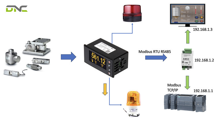
Capacity sizing to this point rests on four inputs and one division
Matching Capacity to the Right Cell Type
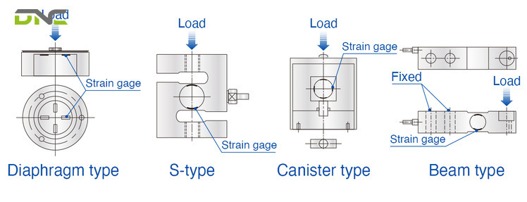
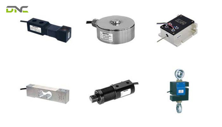
Capacity ranges are not evenly served by every geometry – each band has a body style built for it. Once the required capacity is known, it narrows the shortlist immediately.
| Capacity band | Typical geometries | Typical applications |
| 0.1–50 kg | Single point, bending beam | Packaging machines, balances |
| 1–500 kg | Bending beam | Bench scales |
| 50–5,000 kg | Shear beam, S-type | Pallet scales, tank weighing |
| 5,000 kg – 100 t and above (11,023 lbf – 220,462 lbf) | Canister, ring torsion | Truck scales, weighbridges |
Two traits matter more than the band when parasitic force is present:
- Shear beam cellscarry an interior design that safeguards them from side-loading, which is why they dominate floor scales and hopper weighing.
- S-beam cellsare built for in-line tension and, as both FUTEK and Group Four state, do not perform accurately with extraneous loads. An S-beam in a position that sees side thrust is a specification error no capacity margin fixes.
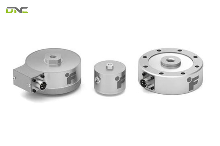
- Pancake cellsare highly resistant to off-axis loading in a low profile, which is what earns them precision work in tight vertical space.
A canister cell and a single point cell can both be correct for the same product weighed on different structures, because the band narrows the shortlist while the loading direction and the side-load exposure decide which entry on that shortlist survives. Capacity and geometry are chosen together, not in sequence. Full treatment of the geometries and the sensing technologies behind them is in Load Cell Types Explained.
Every band above assumes the load settles before it is read. On a moving line it never does.
Matching Capacity to the Right Cell Type
Capacity for Dynamic Weighing: Checkweighers and Weighing Conveyors
In-line weight checking inverts the usual capacity logic, because the product is light, the carrier is not, and the load never stops moving. None of the four ranking guides addresses capacity sizing for a checkweigher, which is a gap worth closing for anyone weighing on a moving line rather than a static platform.
Three pressures pull in different directions:
Resolution wants low capacity. A checkweigher earns its place by detecting small deviations on a small product. Laumas places checkweighers in the C3–C6 accuracy band alongside precision scales, bench scales and weighbridges – the classes that resolve the finest divisions relative to capacity. Every unnecessary kilogram of rating widens the division the checkweigher is trying to read against.
The carrier wants high capacity. The weighing conveyor’s belt, rollers, frame and drive components sit on the cells permanently as dead load, and on a short weigh section they routinely outweigh the product several times over. That is the same tare problem as a hopper, concentrated into a smaller cell.
Motion wants margin. Product transferring onto a moving belt arrives with momentum, not just weight. FUTEK’s selection sequence separates static from dynamic load as a defining characteristic precisely because the sensor’s frequency response and its capacity have to suit a load that appears and disappears within a fraction of a second.
The workable resolution is to strip dead load out of the weigh section rather than absorbing it with capacity: keep the weighing conveyor short, keep the frame light, isolate the drive from the weighed section, and specify the capacity against the carrier plus product plus transfer impact – nothing more. Capacity added “for safety” on a checkweigher is subtracted directly from the sensitivity that justified buying it.
Where checkweighing sits alongside metal detection or vision, the weighing decision belongs with the wider automated inspection systems specification, and the mechanical layout with the conveyor system it runs on.
Dead load, impact and resolution are all set by the machine. The plant around the machine sets the rest.
Checkweighers and Weighing Conveyors
Conditions That Change the Capacity Answer
Environment and duty do not only dictate protection ratings – several of them consume capacity outright. Laumas structures load cell selection around four questions: where do we weigh, how do we weigh, what do we weigh, and why. Applied to capacity, the conditions that shift the number are these.
| Condition | Effect on the capacity decision |
| High ambient temperature | Cells lose capacity as temperature climbs – Galoce cites a 10% loss at 100 °C. Standard thermal compensation runs −10 to +40 °C; beyond it, the working range no longer guarantees metrological performance |
| Ice or accumulation | Galoce adds 15% capacity for ice loading in cold climates; any accumulating deposit is dead load the cell was never told about |
| High humidity | In Southeast Asian conditions Galoce accounts for moisture weight at +2–5% of the measured load |
| Washdown and chemicals | Stainless with IP69K for high-temperature, high-pressure washing; 3-A Sanitary Standard or EHEDG certification where sanitisability must be attested |
| Corrosive or outdoor exposure | Material ladder from aluminium or non-stainless steel indoors, to stainless 420 as a baseline outdoors, to 17-4 PH for maximum corrosion resistance |
| Explosive atmosphere | Certification to the regime that governs the site – ATEX, IECEx, FM HazLoc, EAC Ex or Ex NEPSI. Hydraulic cells contain no electrical components, which makes them the safest option in explosive or lightning-prone locations |
| Seismic or high-wind sites | Anti-tilt constraints and mounting kits must be specified at purchase, not retrofitted |
| Continuous cycling | Operate at 50% or lower of rated capacity, or specify a fatigue-rated sensor – a line running thousands of cycles per hour loads the metal nothing like a one-off test |
Ingress ratings follow the IP code structure: the first digit rates protection against solids from 0 to 6, the second rates liquids from 0 to 9, with IP65 and IP69K covering jets and IP67 and IP68 covering immersion.
Output type matters here too, because capacity decisions are only as good as the signal that carries them. Analog cells output a standard 2 mV/V or 3 mV/V; 4–20 mA suits electrically noisy environments; digital RS-485 or CANbus suits multi-cell arrangements. Matching that output to the controller is part of the same specification pass as smart manufacturing integration, and bridge resistance – usually 350 or 1,000 ohms – has to match the instrument driving it.
One entry on that list of conditions is not physical at all: what the weighed number will be used for.
Capacity Certification for Legal-for-Trade Weighing
If the weighed value determines a price, the capacity you choose has to come with an approval attached. Laumas is clear that legal-for-trade use requires an approved cell carrying OIML R60 metrological certification, which attests compliance with the requirements set by the International Organization of Legal Metrology.
The accuracy class notation encodes what that approval delivers. A letter – A, B, C or D – expresses the accuracy level, and the number that follows states how many legal divisions the cell can measure, in thousands. Class C3 therefore describes a cell that supports weighing systems resolving 1/3,000 of maximum capacity. Class D1 is acceptable for construction material; C3 through C6 and above serve precision scales, checkweighers, approved weighing systems, bench scales and weighbridges.
| Specification | What it tells you |
| OIML accuracy class | Accuracy level and number of legal divisions |
| Combined error | Linearity, hysteresis and temperature error summed as a percentage of full scale – lower is better |
| V<sub>min</sub> | Maximum capacity ÷ the value from OIML testing; the smallest increment the cell can measure |
| Effect of temperature on zero and full scale | Reading drift per degree, as a percentage of full scale |
Regional approvals sit alongside OIML R60: NTEP Class III in the United States, CPA in China, PAC in the Russian Federation. Which approval applies is decided by the jurisdiction governing the transaction, not by the cell manufacturer – establish the requirement with the authority governing your trade use before the order is placed, because an unapproved cell cannot be certified retrospectively.
Where weighing is internal – batching, load limitation for safety, quality checking, piece counting, statistical checks on prepackaged goods – the accuracy class remains a useful specification even though approval is not compulsory. Laumas’s own framing is that the value of the goods sets the accuracy required: sand and gravel tolerate what pharmaceutical batching cannot.
Approval regimes are decided by jurisdiction. Operating conditions are decided by geography.
Capacity Certification for Legal-for-Trade Weighing
Capacity Sizing in Malaysian Plants
Every leading selection guide on this query is written for a different climate. The four ranking sources originate in China, the United States, Italy and Japan, and their environmental assumptions follow. Malaysian production conditions change several inputs at once.
Humidity is continuous, not seasonal. Galoce’s Southeast Asia guidance assumes around 90% humidity with monsoon rain, and accounts for moisture weight at +2–5% of the measured load – material absorbs water, and hygroscopic powders keep absorbing it in an open hopper. That is dead load and product weight moving together.
Washdown is routine in the sectors that dominate. Food and beverage, glove manufacturing and edible oils all run wet cleaning cycles with chemical detergents at temperature and pressure. That pushes the specification to stainless with IP69K protection, and where sanitisability has to be attested, to 3-A Sanitary Standard or EHEDG certification. It also means cable entry orientation is a real decision – side versus bottom entry changes how water behaves at the gland.
Ambient heat runs at the top of the compensated band. Standard thermal compensation of −10 to +40 °C covers Malaysian ambient conditions, but process-adjacent installations – near ovens, dryers, sterilisers, oleochemical process lines – leave it quickly, and beyond the compensated range the data-sheet errors no longer apply.
Product density varies more than the equipment does. A hopper sized for one material and later run with a denser one is a common route to overload, and it is a paperwork problem rather than an engineering one.
None of this changes the formula. It changes the numbers going into it – which is why capacity is specified against the installation, not against the catalogue.
Summary: what the environment changes
The specification arrived at earlier now carries conditions attached. Temperature, ice and moisture each add or remove usable capacity before the process load is counted, which moves the number rather than the method. Washdown duty, corrosive exposure and explosive atmospheres decide construction material and certification, and those decisions restrict which capacities exist to choose from. Legal-for-trade duty adds an approval that must be in place before the order, since it cannot be granted afterwards. Continuous cycling caps the usable fraction of the rating at around half. Malaysian plants stack several of these conditions at once – continuous humidity, routine washdown, and ambient temperature sitting near the top of the compensated band. Taken together, they explain why two plants weighing the same product specify different cells: the load is identical and the duty is not.
Five Capacity Mistakes That Shorten Load Cell Life
Five Capacity Mistakes That Shorten Load Cell Life
- Sizing from the product weight alone.The dead load of the tank, hopper, platform or weighing conveyor is permanent and frequently larger than the material. The bagging example above ran 78% structure.
- Treating shock as an allowance.Sources put dropped-material impact at 3–5 times the static weight, and a weight dropped onto a scale at up to 10 times. The spread is real and depends on drop height and material – which is the argument for measuring the drop rather than picking a number. Either figure demolishes a cell specified against the static load.
- Ignoring side load.Effective capacity falls 20–30% when load does not arrive on the design axis. The fix is mechanical, not a larger cell: load buttons, rod-end bearings, anti-tilt constraints, or a geometry built for it such as shear beam or pancake.
- Buying capacity as insurance.Extra rating coarsens every division. Beyond the duty ladder, oversizing spends resolution to buy survival the margin already provided.
- Specifying the cell without the instrument.A load cell produces a millivolt signal and nothing else. Group Four and FUTEK both recommend ordering sensor and instrument as a matched pair with system calibration, and FUTEK notes that a custom sensor adds at least a month to delivery – a timeline worth knowing before the line is scheduled.
Each of the five traces back to one of the four weights, or to the margin applied over them.
Frequently Asked Questions
Six questions recur whenever load cell capacity reaches a sizing review, and each one turns on the margin the nameplate rating leaves unstated. The answers below use the same safe-load and dead-load allowances applied earlier, so a figure quoted here can be carried straight into a specification.
What capacity load cell do I need for a 1,000 kg tank?
Not 1,000 kg. Add the tank and frame weight, multiply by a dynamic factor for how material is loaded, then by a safety factor for the duty. Galoce’s worked case of a 1,000 kg tank on a 200 kg hopper at 1.3 × 1.5 gives 2,340 kg, specified as a 2,500 or 3,000 kg cell – and divided across the cells actually supporting the tank.
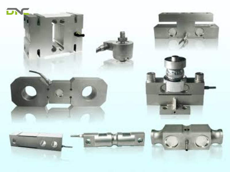
What capacity load cell do I need for a 1,000 kg tank?
Is it better to oversize or undersize a load cell?
Oversize, but only to the margin the duty requires. Undersizing risks mechanical failure and a safety hazard; oversizing is recoverable but permanently costs resolution. Published guidance runs from 20–30% for static clean loads up to 100% or more for unpredictable distribution, with cycling applications operating at 50% or less of rated capacity.
How do I calculate capacity for a 4-cell platform?
Calculate the total requirement first – all four weights and the margin – then divide by four and round up to the next standard rating. Do not reduce the margin because the load is shared: sharing lowers the average each cell sees, not the maximum, and unbalanced discharge or an off-centre agitator pushes load into some cells and not others.
Does a bigger load cell reduce accuracy?
It costs resolution, which shows up as accuracy at the light end, in cases where the product is light relative to the rating. A class C3 cell resolves 1/3,000 of maximum capacity, so a 6,000 kg cell reads in 2 kg divisions where a 3,000 kg cell reads in 1 kg. On a light product weighed on a heavy structure, that difference decides whether the system is usable.
What accuracy class do I need for a checkweigher?
Checkweighers sit in the C3–C6 band alongside precision scales and weighbridges. Reaching that in practice depends as much on keeping the weighing conveyor’s dead load down as on the class printed on the cell.
Can I use a standard load cell for washdown areas?
Not if washing is done with hot, pressurised water and chemical detergents. That duty calls for stainless construction with IP69K protection, and where sanitisability must be demonstrated, 3-A Sanitary Standard or EHEDG certification. Material choice runs from aluminium or non-stainless steel indoors, to stainless 420 outdoors, to 17-4 PH where corrosion resistance is critical.
Capacity is the specification that every other weighing number is measured against, and it is decided once – before the frame is built and before the cells are ordered. If you are sizing cells for a tank, weigh hopper, checkweigher or packaging line, DNC’s engineering team works the four weights against your actual installation, divides the requirement across the mounting arrangement, and matches the output to the controller already on your line – Get a Free Consultation before the mechanical design is fixed.
- 24 views
- 0 Comment
Recent Comments