


Load Cell Types Explained: Technologies, Shapes & Selection
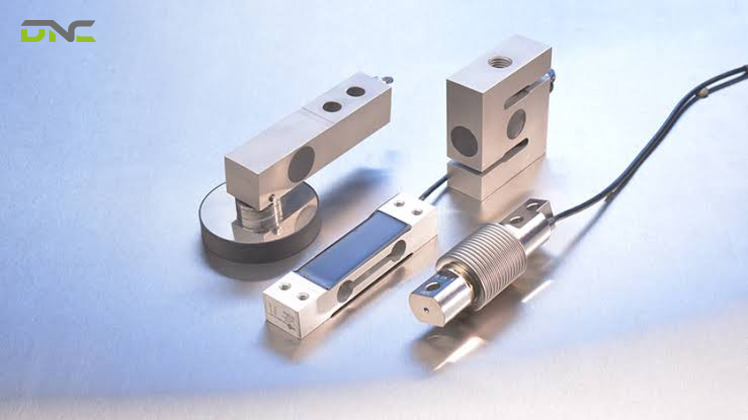
Load Cell Types Split Across Two Independent Axes
From a specification standpoint, a load cell has two type designations at once: one sensing technology and one body geometry. The two are independent. A pancake cell and an S-beam cell are both strain gauge cells built in different shapes; a hydraulic cell and a capacitive cell answer the same question – how does force become a signal – with entirely different physics.
Most reference material collapses these into a single list, placing “hydraulic load cell” beside “pancake load cell” as if they were alternatives. They are not alternatives. Sensing technology determines what the sensor can survive: explosive atmospheres, washdown chemicals, impact events, temperature swing. Body geometry determines where the sensor fits and which direction the load arrives from.
The practical consequence shows up during specification. An engineer who selects “strain gauge” has narrowed nothing about mounting, and an engineer who selects “S-beam” has narrowed nothing about hazardous-area compliance.
| Axis | What it answers | Options |
| **Sensing technology** | How force becomes an electrical signal | Strain gauge, hydraulic, pneumatic, capacitive, piezoelectric |
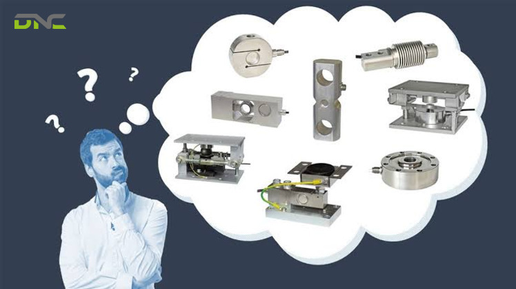
| **Body geometry** | How force enters the sensor and where it mounts | Single point, shear beam, S-beam, compression column, pancake, donut, load button, multi-axis |
Sensing technology comes first in the specification sequence, because environment eliminates options faster than mounting does.
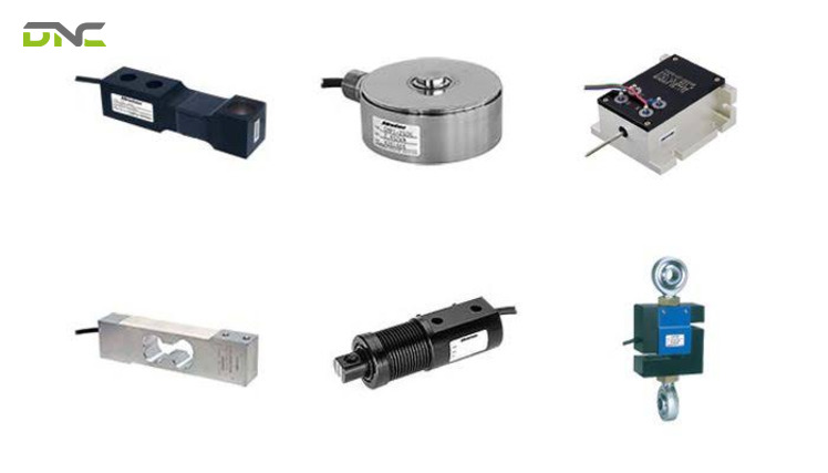
Load Cell Types Split Across Two Independent Axes
Five Sensing Technologies Convert Force Into Signal
Five sensing technologies cover industrial force measurement: strain gauge, hydraulic, pneumatic, capacitive, and piezoelectric. Each exploits a different physical property – electrical resistance, fluid pressure, air balance, capacitance, or crystal charge – to produce an output proportional to load. Two of the five borrow their physics from fluid power: hydraulics and pneumatics both convert load into a balanced pressure rather than a strain measurement. Only strain gauge cells are general-purpose. The other four exist because specific environments disqualify the default.
Strain Gauge Load Cells Carry the Industrial Default
Strain gauge load cells are the most prevalent type across industrial weighing, force testing, and material handling, measuring from 5 N (0.51 kgf / 1.12 lbf) to over 50 MN (5,099 tonnes-force) according to IQS Directory’s 2026 load cell classification reference. The sensing element is a precision-machined spring element that flexes predictably under load. Bonded to it, ultra-thin conductive gauges stretch or compress with the metal, changing cross-sectional area and therefore resistance.
Four gauges wired into a Wheatstone bridge convert that resistance change into a measurable voltage imbalance. Basic single-point and bending beam cells use four gauges; high-precision multi-axis cells integrate up to thirty in a full bridge configuration for sensitivity and error compensation.
The constraint is electrical. Strain gauge cells are passive transducers requiring excitation voltage, which rules them out where power is unavailable or where sparks are unacceptable. Output sits in the millivolt range and needs EMI shielding plus signal conditioning to produce clean data.
Hydraulic Load Cells Remove Electricity From the Measuring Point
Hydraulic load cells measure force as fluid pressure inside a sealed chamber. A piston presses an elastic diaphragm, the enclosed oil pressurises proportionally, and a Bourdon tube or pressure gauge reads the result. Tacuna Systems specifies typical capacity up to 5 MN (510 tonnes-force / 1,124,000 lbf), accuracy of 0.25 to 1.0 percent of full-scale output, and resolution near 0.02 percent.
No electrical circuit exists at the point of measurement. That single property is why hydraulic cells are specified for ATEX and Class 1 hazardous zones – the ignition source is removed rather than shielded – and why lightning strikes and electrical surges that destroy a strain gauge system leave them unaffected.
The same non-electrical path costs stability. Hydraulic fluid expands and contracts with ambient temperature, producing zero drift: the scale reads a value with nothing on it. Outdoor installations need re-zeroing or temperature-compensated fluid systems.
Pneumatic Load Cells Balance Load Against Regulated Air
Pneumatic load cells operate on force balance. Load presses one side of a high-precision diaphragm while regulated air pressurises the opposite chamber, and a nozzle bleeds air until internal pressure balances the applied force exactly. The balancing pressure is the measurement. Gas compresses more readily than liquid, so these cells detect very small weight changes.
Pneumatic cells introduce no fluid that could contaminate a process. That makes them the technology of choice for medical dispensing, pharmaceutical clean rooms, and high-precision food processing, where an oil leak is a safety violation rather than a maintenance ticket.
Maintenance demand is the trade. Accuracy depends on air regulator quality and a clean nozzle, and small amounts of moisture or debris introduce measurement error.
Capacitive Load Cells Tolerate Hermetic Sealing
Capacitive load cells measure the gap between two parallel conductive plates. Load deflects the structure, the gap narrows, and capacitance shifts proportionally to the applied force. Internal electronics translate the stored-charge change into a reading.
The sealing property is what distinguishes them. Capacitive cells can be hermetically sealed without compromising operation, which suits sterilisation cycles, laboratory balances, and automatic checkweighers. They resist side loads and overload, and their simple construction keeps cost below several alternatives.
Two constraints apply. The dielectric between the plates responds to temperature fluctuation and may need compensating electronics, and because capacitance changes are small, unshielded cabling admits electrical noise.
Piezoelectric Transducers Measure Events, Not Weights
Piezoelectric transducers generate their own charge. Mechanical stress deforms a crystal lattice – quartz or a specialised ceramic – internal dipoles shift, and electrodes collect a charge proportional to load. The crystal is rigid, so deflection is nearly zero and response is close to instantaneous.
Charge is generated when the lattice deforms, not while it stays deformed. Charge then leaks away through the amplifier input, so a constant weight decays toward a zero reading. Piezoelectric cells therefore measure the event – a press strike, an impact, a vibration peak – and cannot measure static loads at all.
That limitation defines their application set: crash testing, ballistics, vibration monitoring, and press-fit operations where peak force matters more than resting mass. A machine frame that vibrates under normal operation suits this technology; a frame holding a settled weight does not.
Piezoelectric Transducers Measure Events, Not Weights
Body Geometry Decides How Force Enters the Sensor
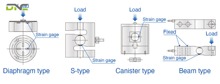
Within a single sensing technology, body geometry determines mounting method, force direction, capacity band, and tolerance to off-axis loading. Eight geometries cover most industrial installations. The table below lists each with its published capacity span and its behaviour under loads that arrive off the primary axis.
| Geometry | Force direction | Typical capacity span | Off-axis tolerance | Where it mounts |
| Single point | Compression | 1–500 kg in aluminium alloy, to 2 t (2,000 kg) in industrial series | Tolerates off-centre load by design | Small platform and bench scales, bottle filling |
| Shear / bending beam | Compression | 1–500 kg low capacity, beam types to 5 t (5,000 kg) | Moderate; needs level mounting | Floor scales, silo and tank legs |
| S-beam | Tension and compression | 25 kg to 10 t (10,000 kg); miniature series from 10 g | Rejects torque and side load | In-line, hanging scales, suspended hoppers |
| Compression column / canister | Compression | 250 kg to several hundred tonnes; 907–13,608 kg (2,000–30,000 lb) mid-range | Axial only | Truck scales, silos, tank weighing |
| Pancake / low profile | Tension and compression | 23 kg to ~454 t (50 lb to 1,000,000 lb) | Resists extraneous moments, including torque | Press frames, material test rigs, tank weighing |
| Donut / thru-hole | Compression through a central bore | Bolt-load and clamping range | Axial through the bore | Bolt clamping force, rod pass-through, rolling mills |
| Load button | Compression | 0.45–45,359 kg (1 lb to 100,000 lb), 6–76 mm OD (¼ in to 3 in) | Requires clean axial load | Confined spaces, bearing load measurement |
| Multi-axis | Fx, Fy, Fz plus Mx, My, Mz | Varies by series | Measures off-axis components instead of resisting them | Robot wrists, assembly force feedback, aerospace test |
Spring element material tracks capacity band. Low-capacity single point and bending beam cells are machined from aluminium alloy; heavy-duty shear beam, canister, and column cells use hardened or corrosion-resistant stainless steel, including martensitic grades in civil engineering series.
Shape is how these are catalogued, and off-axis tolerance is how they behave in service. The geometries form a spectrum: S-beam cells reject moments and lose accuracy when loaded off centre, pancake cells resist extraneous torque better than any in-line style, single point cells accept off-centre loading as a design feature, and multi-axis cells measure the off-axis components as separate channels.
Single point and S-beam cells sit at opposite ends of that spectrum despite both being strain gauge devices – which is exactly why the two axes cannot be merged into one list.
Once geometry fixes the mechanical interface, output type fixes the electrical one.
Body Geometry Decides How Force Enters the Sensor
Analog and Digital Outputs Change the Wiring, Not the Measurement
Every load cell begins analog: the bridge produces a small voltage in millivolts per volt of excitation, and the difference between an analog and a digital cell is where that signal gets converted. Encardio-Rite specifies a bridge excited at 10 V DC producing full-scale output near 1.5 mV/V. Sensitivity stated as 3 mV/V means 3 mV of output at nominal force per 1 V of input.
A full-scale signal in the low tens of millivolts then travels down a cable inside a machine frame. Long analog runs routed beside VFD and motor cabling attenuate and pick up interference, and signal loss over distance is a documented weakness of analog cells. The cable is the failure point, not the sensor.
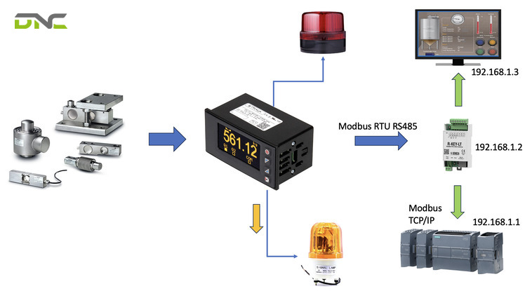
Digital cells move the analog-to-digital converter onto the sensor and transmit over RS485 or CANbus. The transmitted value resists electromagnetic disturbance, radio frequency interference, and temperature-driven noise, and the protocol carries per-cell diagnostics, remote calibration, and simultaneous collection from multiple load points.
Output options across both families include analog voltage, 4–20 mA current, frequency, digital serial over RS232 or RS485, parallel, and relay or alarm functions. The selection question is not which output is better – it is which input already exists on the controller. A cell specified without reference to the PLC analog card or the DAQ channel count creates an integration cost that surfaces at commissioning. Specifying the sensor and the controller input together is the difference between a component purchase and a working measurement chain, which is where smart manufacturing architecture and sensor selection meet on the factory floor.
A component vendor sizes the cell. An integrator sizes the cell, the conditioner, the controller input, and the cable route.
Accuracy Class, %RO, and IP Rating Define What the Cell Guarantees
Load cell accuracy class, %RO, and IP rating are three independent qualification labels, each governing a different failure risk. A cell that satisfies its accuracy class still fails the process when its %RO resolution or its sealing falls short.
Accuracy classes run A, B, C, and D, with Class A the highest precision and the most verification intervals across its measuring range. The International Organization of Legal Metrology sets these classes internationally, the National Institute of Standards and Technology governs them in the United States, and the National Type Evaluation Program certifies equipment for legal-for-trade use in the US market. Commercial weighing scales are typically certified to OIML class C3, while force-testing and R&D installations reference ASTM E-74 instead. Cells outside these schemes are labelled general purpose and often deliver comparable accuracy where legal-for-trade rules do not apply.
OIML labelling on a certified cell states rated capacity, accuracy class, number of divisions, the force direction it is built for – compression, tension, beam, or universal, marked with a directional arrow – plus temperature rating and humidity rating, coded SH for steady humidity or NH for no humidity.
Accuracy class alone does not tell an engineer what the machine will read. Rated output does. At ±0.5 %RO, a 10,000 kg (10 t / 22,046 lb) cell resolves to ±50 kg (110 lb), per Encardio-Rite’s published accuracy definition. That figure is acceptable for a truck weighbridge and useless for a 5 kg fill weight. Because the error band scales with rated output, oversizing capacity destroys resolution – the most expensive mistake in routine load cell specification.
Ingress protection follows IEC 60529. The first digit rates solid ingress from 0 to 6, the second rates liquid ingress from 0 to 8, and industrial or outdoor installations commonly require IP67 or IP68.
| Rating element | Range | What it covers |
| First digit | 0–6 | Solids, from no protection to total dust exclusion |
| Second digit | 0–8 | Liquids, from no protection to continuous immersion |
| Common industrial specification | IP67 / IP68 | Washdown, outdoor, dusty plant environments |
One number hides two constructions. Potting fills the cavity with epoxy or resin and protects circuits from humidity and damage; hermetic sealing welds the enclosure airtight. Permanently submerged service – marine weighing, underwater platforms, flooded pits, dry docks – needs hydrostatically compensated cells in all-stainless construction, a category beyond any IP number. An IP67 potted cell and an IP67 fully welded cell carry the same label and behave differently after two years of daily caustic washdown. ATEX and FM certificates apply separately, and they matter for facilities releasing flammable vapours or handling fine organic dusts such as grain flour and wood dust.
Metrology traceability extends past the sensor to the system. DNC Automation’s ISO 9001:2015 quality framework treats the calibrated chain – cell, conditioner, indicator – as one qualified assembly, the same principle applied in automated inspection systems where measurement validity determines whether a reject decision is defensible.
Accuracy Class, %RO, and IP Rating Define
Summary So Far: What the Four Specification Layers Decide
Load cell specification has produced four decisions to this point. Sensing technology – strain gauge, hydraulic, pneumatic, capacitive, or piezoelectric – answers what the sensor survives, from ATEX zones to washdown chemistry to impact events. Body geometry answers where the sensor mounts and how much off-axis load it tolerates, ranging from single point cells that welcome eccentric loading to S-beam cells that reject it. Output type answers how the reading reaches the controller: a 1.5 mV/V analog signal down a shielded cable, or a digital value over RS485. Accuracy class and %RO answer what the reading guarantees, while the IP number and its underlying construction answer how long that guarantee survives the plant floor.
Load Cell Selection Runs Constraint First, Type Second
Specify the environment before the sensor, because environment eliminates whole technologies while capacity only narrows a range. Six steps produce a complete specification.
- Classify the environmental constraint.Hazardous or unpowered locations route to hydraulic or pneumatic. Sterile and washdown processes route to capacitive or hermetically sealed strain gauge. Impact and vibration route to piezoelectric. Everything else routes to strain gauge.
- Set rated capacity against peak load, then check resolution.Include shock and dynamic overshoot in peak load, then convert the accuracy class into an absolute figure using %RO before accepting the capacity.
- Identify off-axis loading and set the capacity band.Off-centre platform loads point to single point geometry, torque-bearing frames point to pancake, and multi-directional force points to multi-axis. Mettler Toledo states the capacity rule plainly: beam types below 10 t of scale capacity, canister or ring cells beyond 10 t, S-type for tension.
- Match output and sampling rate to the controller already installed.Analog voltage or 4–20 mA suits a short run into an existing PLC analog card; RS485 or CANbus suits long runs, multiple cells, or diagnostics requirements. Sampling requirements split into three bands – 1 Hz for static weighing, up to 100 Hz for in-motion checkweighing, above 100 Hz for impact and press force capture.
- Specify the sealing construction, not just the IP number.State potted or fully welded hermetic explicitly, and add ATEX or FM where the atmosphere requires it.
- Specify mounting hardware and alignment tolerance.Force must pass centrally and axially through the cell, so the frame determines the number the controller receives.
Procurement habit inverts this sequence, starting from capacity and price and treating environment as a later adjustment. That order produces oversized cells with unusable resolution and sealing that fails its first washdown season. Constraint-first specification costs nothing extra at the quotation stage.
Load cells rarely arrive alone. They sit on a weighing frame feeding a filler, a checkweigher on a conveyor system, or a force channel inside a press cell, and the surrounding equipment sets the mounting and the controller interface as firmly as the measurement requirement does.
Four Failure Modes Account for Most Load Cell Readings That Drift
Four failure modes cause most load cell readings that drift: overload deformation, eccentric loading, thermal shift, and cable interference. Each produces a distinguishable symptom, which makes field diagnosis a matter of matching the pattern before replacing hardware.
| Symptom | Cause | Countermeasure |
| Zero balance will not return after unloading | Overload has permanently deformed the spring element or damaged gauges | Specify mechanical stops, calibrated overload screws, or pretensioned springs; add capacity margin for shock |
| Reading changes with load position on the platform | Side or eccentric loading; forces not passing centrally and axially | Switch to single point geometry, correct frame alignment, or perform corner adjustment |
| Reading drifts with ambient temperature | Thermal expansion of hydraulic fluid or dielectric material | Use temperature-compensated fluid, re-zero on schedule, or move to a compensated strain gauge cell |
| Unstable, noisy signal on long cable runs | Electromagnetic interference on a low-millivolt analog line | Shield and reroute the cable away from drives, or specify a digital output cell |
Mechanical damage, broken cables, moisture ingress, and corrosion produce overlapping symptoms, so a structured sequence – visual inspection, zero balance check, insulation verification on non-hermetic cells, then bridge resistance and continuity tests – isolates the fault faster than component swapping. Mounting orientation deserves a check of its own: an inverted tension or S-beam cell returns negative or false readings.
Force feedback in robotic assembly raises the same specification questions in a moving frame, where multi-axis cells feed cross-talk-compensated vector data into the controller. Force-controlled insertion in industrial robotic solutions depends on that channel behaving predictably under exactly the off-axis conditions this section describes.
Four Failure Modes Account for Most Load Cell Readings That Drift
Load Cell Types – Frequently Asked Questions
Seven questions recur whenever load cell types reach a specification review, and each one turns on the two-axis distinction that a single flat type list leaves implicit.
What Are the Main Types of Load Cells?
Load cells are classified two ways at once. By sensing technology there are five: strain gauge, hydraulic, pneumatic, capacitive, and piezoelectric. By body geometry there are eight common forms: single point, shear beam, S-beam, compression column, pancake, donut, load button, and multi-axis. Strain gauge cells account for most industrial installations, and any geometry in the second list can be built as a strain gauge cell.
Which Load Cell Type Is Most Accurate?
Capacitive and strain gauge cells deliver the highest accuracy and sensitivity among the five sensing technologies, with pneumatic and hydraulic cells trailing on both counts. Accuracy in service depends more on correct capacity sizing than on technology choice, because rated output error scales with capacity – a 10,000 kg cell at ±0.5 %RO resolves only to ±50 kg regardless of how well it is built.
What Is the Difference Between a Load Cell and a Strain Gauge?
A strain gauge is a single resistive element; a load cell is a complete assembly of strain gauges wired into a Wheatstone bridge on a spring element. The gauge converts deformation into a resistance change. The load cell adds the mechanical structure that receives force, the bridge circuit that makes the resistance change measurable, and the housing that protects both.
How Do Analog and Digital Load Cells Differ?
Analog cells transmit the raw millivolt bridge output for external conversion; digital cells convert on board and transmit data over RS485 or CANbus. Analog suits short cable runs into an existing PLC analog input. Digital resists electromagnetic interference over long runs and supports diagnostics, remote calibration, and simultaneous readings from multiple cells.
What Does Load Cell Accuracy Class Mean?
Accuracy class rates measurement precision on a four-level scale – A, B, C, D – with Class A highest and Class D lowest. OIML sets the classes internationally and NIST governs them in the United States. Commercial scales are typically certified to OIML class C3. Class determines legal-for-trade eligibility; %RO determines the actual resolution your process will see.
Can a Piezoelectric Load Cell Measure Static Weight?
No – piezoelectric transducers cannot measure static loads. The crystal generates charge only while deforming, and that charge leaks away, so a constant weight decays toward zero. Piezoelectric cells measure dynamic events including impacts, shocks, vibration peaks, and press-fit forces. Static weighing requires strain gauge, hydraulic, pneumatic, or capacitive technology.
What IP Rating Does a Load Cell Need for Washdown?
Washdown environments call for IP67 or IP68 with hermetic sealing, not potting. IEC 60529 rates solid ingress on the first digit and liquid ingress on the second, but the rating alone does not state construction. A potted cell and a fully welded cell can share an IP67 label and diverge sharply in service life under daily caustic cleaning.
Load cell specification resolves in a fixed order: environment selects the sensing technology, load path selects the geometry, capacity and %RO together set the usable resolution, and the controller input selects the output type. Reversing that order is what produces oversized cells, failed sealing, and noisy signals on a running line.
For Malaysian manufacturers building toward NIMP 2030 automation targets, load cells are rarely a standalone purchase – they are one channel inside a filling, palletising, inspection, or press system that has to be commissioned as a whole. DNC Automation’s engineering team has specified sensing and control hardware across automotive, food and beverage, glove manufacturing, and edible oils facilities since 2005, across more than 1,000 automation projects.
If your facility is specifying load cells as part of a weighing, filling, or force-control application, DNC’s 35 engineers match the technology, geometry, and output type to your line and your existing controller architecture – Get a Free Consultation to scope the measurement chain before hardware is ordered.
- 20 views
- 0 Comment
Recent Comments