


MCC Panel: Meaning, Components, Types and Specification
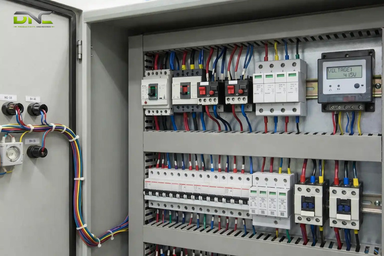
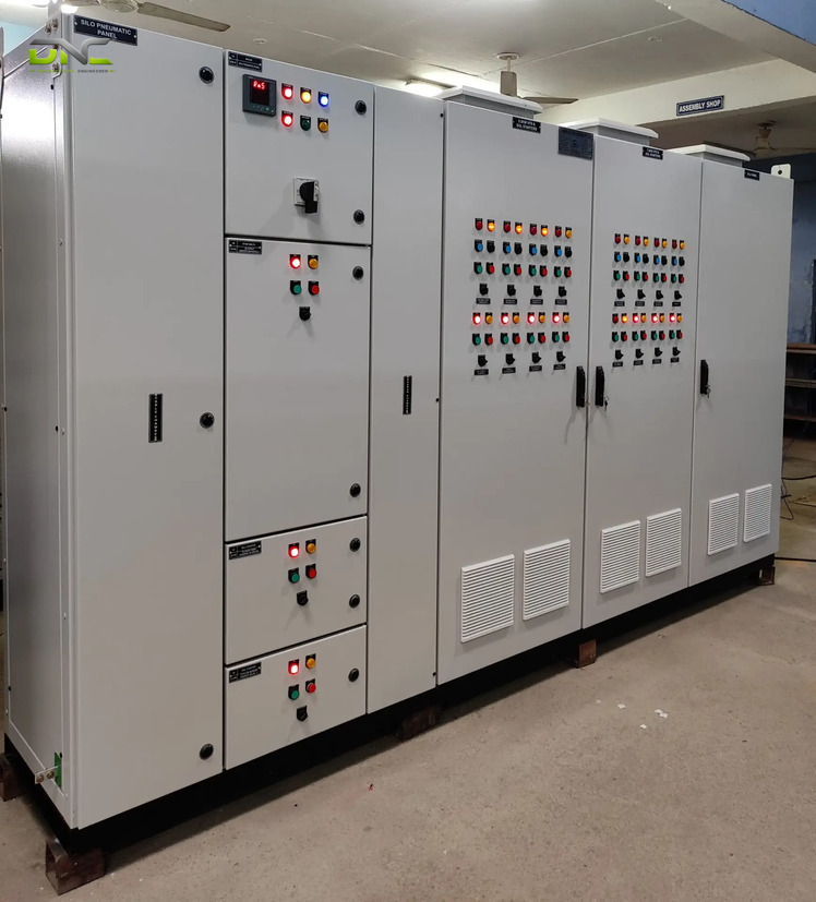
An MCC panel (motor control center panel) is a low-voltage assembly of enclosed sections that share one power bus, with a separate starter feeder for each motor. Each feeder combines a circuit breaker or fuse, a contactor and an overload relay. A feeder holds a direct-on-line starter, a soft starter or a variable frequency drive (VFD), depending on the motor.
The motor control center centralises start, stop and short-circuit protection for pumps, fans and conveyors, and a programmable logic controller (PLC) commands the feeders. Five decisions define the MCC panel: the motor list, the starter type per motor, the construction type, the form of separation and the fault level. Specifiers settle all five before a supplier prices the panel, including a Siemens drive and PLC supplier such as DNC Automation.
MCC Panel Meaning: Motor Control Center Defined
MCC panel meaning is motor control center: an assembly of one or more enclosed sections having a common power bus and principally containing motor control units, in the wording the Wikipedia entry quotes from NFPA 70, Article 100. Each section holds a combination starter. That starter is a motor starter, fuses or a circuit breaker, and a power disconnect in one unit.
“MCC panel” and “motor control center panel” name the same assembly. UK and Indian sources spell it “centre”. The MCC panel full form is therefore the same in every spelling.
Low-voltage motor control centers serve three-phase AC motors from 220 V to 600 V. Medium-voltage versions serve large motors from 2,300 V to about 15,000 V (15 kV), with vacuum contactors and separate compartments for power switching and control, per Wikipedia. Automobile plants have used motor control centers since 1950 because they run large numbers of motors.
A distribution board only distributes power. An MCC panel adds a motor control unit to every outgoing circuit, which is why panel makers separate the two. DNC Automation lists MCC and motor control next to its Siemens drive and PLC supply for Malaysian factories.
The words “motor control panel” cover more than this definition, and the next section draws the line.
Motor Control Panel vs MCC Panel: One Starter or a Shared Bus
A motor control panel is any enclosure that starts and protects a motor, while an MCC panel is the multi-motor assembly with a shared power bus. One industrial supplier’s guide describes the starter panel as the plainest motor control panel: it houses the starter for one electric motor, with a breaker. The same guide lists distribution panels, motor control centers and combination starter panels as other kinds.
The table sorts the three situations a buyer of an MCC panel meets.
| Situation | Panel that fits | Why |
| One motor on one machine | Starter panel (motor control panel) | One starter, one breaker, mounted by the machine |
| Several motors in one process area | MCC panel | One shared bus, one feeder per motor |
| Many circuits from one transformer | PCC panel, then MCC panels | The PCC distributes; the MCC controls motors |
The same loads recur on every page that describes the MCC panel: pumps, fans, compressors, conveyors, blowers and mixers. A Malaysian M&E supplier describes its MCC panel as feeders for motors and blowers, sized to each motor rating. That supplier adds a point most guides skip. Manual provision lets an operator run a motor by hand, and auto provision waits for an external signal from the control panel.
The shared bus is the part that a motor control panel for a single motor lacks, so the components below start there.
MCC Panel Components: Incomer, Busbar and Feeder Unit
MCC panel components fall into three groups: the incomer that receives power, the busbar that carries it, and one feeder unit per motor. The table lists each group and the range one vendor’s guide publishes for its parts.
| Component | Job | Range in one vendor’s guide |
| Incomer circuit breaker | Receives and protects the supply | 400 V to 690 V rating |
| Busbar | Carries power to every feeder | Copper or aluminium |
| Contactor | Switches the motor on and off | 24 V to 440 V coil voltage |
| Overload relay | Trips on excess motor current | 0.5 A to 630 A range |
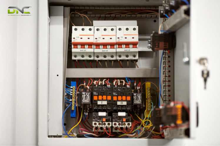
The feeder unit is the repeating part. Per Wikipedia, each motor controller holds a contactor or solid-state controller, overload protection, fuses or a circuit breaker for short-circuit protection, and a disconnecting switch. Control parts sit beside them: push buttons, selector switches, indication lamps, auxiliary contacts and PLC input and output terminals.
Pairing matters as much as the parts in an MCC panel. Under IEC 60947-4-1, type 2 coordination means the contactor and its overload device remain serviceable after a short circuit that the upstream protection clears, according to one panel maker. Smaller units unplug from the cabinet for testing, while very large ones bolt in place.
Twelve motors give an MCC panel twelve feeders. The count comes from derived arithmetic, and it shows why the feeder, not the enclosure, is the unit of specification.
Power reaches a feeder along a fixed path, which the MCC panel working principle follows from the incomer to the motor.
MCC Panel Components: Incomer, Busbar and Feeder Unit
MCC Panel Working Principle: From Incomer to Motor
The MCC panel working principle is a power path in four steps: incomer, busbar, feeder, motor. The list follows that path in the order the power travels.
- The MCC incomer takes the supply, usually as a feeder from the PCC (power control center), through a main breaker.
- The busbar spreads that supply to every feeder in the line-up.
- The feeder closes its contactor when it receives a start command, while the breaker and the overload protection watch the motor current.
- The motor runs until a stop command or a protective trip opens the contactor.
An MCC panel does not sequence motors by itself. Automatic operation needs control circuits, sensors or PLC logic, per one panel maker. In an engineered assembly, internal control and interlock wiring runs to a central terminal board or to a programmable logic controller, according to Wikipedia.
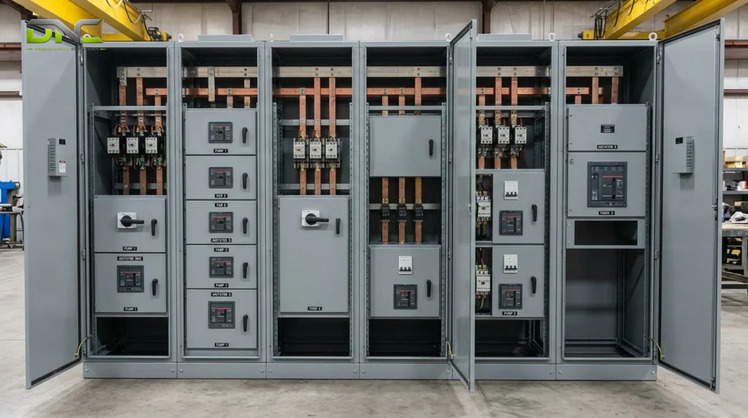
Each step maps to a physical part. The incomer is a breaker, the busbar is a copper or aluminium conductor, the feeder is a contactor with its protection, and the motor is the load. A hard-wired start command and a network start command reach the same contactor. Cabling separates the two, and the intelligent MCC section below returns to it.
Which starter sits behind that contactor depends on the motor, and the next section compares the four MCC panel starters.
MCC Panel Working Principle: From Incomer to Motor
MCC Panel Starter Types: DOL, Star-Delta, Soft Starter and VFD
MCC panel starter types are direct-on-line (DOL), star-delta, soft starter and VFD, and the motor, not the panel, decides which one a feeder holds. Different feeders in one MCC panel can use different starters. The table compares them.
| Starter | What it does | Fit |
| DOL | Connects the motor straight to the supply | Small motors, typically up to about 45 kW (60 hp) on a strong supply, per one panel maker |
| Star-delta | Starts in star, then switches to delta | Larger motors with light starting loads; one maker lists up to 250 kW (335 hp) |
| Soft starter | Ramps voltage at start, with controlled stop on some models | Loads that run at one speed |
| VFD | Varies frequency and voltage, so speed follows the process | Variable-speed pumps, fans and conveyors |
In an MCC panel, DOL starts the motor at full voltage, and the Wikipedia entry on variable-frequency drives puts DOL inrush at up to 8 times full-load current. Star-delta cuts the starting current to roughly one-third, and a second panel maker notes that it also cuts starting torque during the star period. The soft starter limits current and mechanical stress but does not control speed after the ramp.
The choice between the last two MCC feeder starters follows one test. A soft starter fits when the load runs at one speed and only the start needs softening. A VFD fits when the process needs speed control after the start. DNC Automation supplies the Siemens frequency inverter range and lists VFD and soft starter panels for these feeders.
Starter choice settles each motor, and MCC panel construction settles what happens to the line when one of those starters fails.
Summary: What an MCC Panel Fixes Before Construction Is Chosen
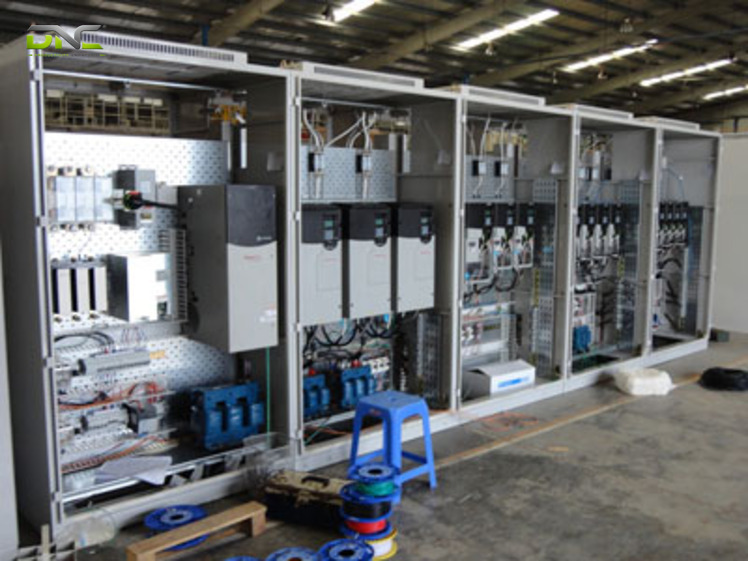
An MCC panel fixes four things before the construction type is chosen. The motor list gives one feeder per motor. The motor and load give the starter: DOL, star-delta, soft starter or VFD. The incomer and the PCC feeder give the supply and the fault level. The control interface decides whether a PLC commands each feeder by hard-wired terminals or by network.
Construction stays open for the MCC panel, and it decides whether servicing one starter takes other motors off.
What an MCC Panel Fixes Before Construction Is Chosen
Types of MCC Panel: Fixed, Semi-Drawout, Drawout and Intelligent
Types of MCC panel differ in how a starter unit is mounted and what happens to the rest of the line when that unit is serviced. Four types recur across panel makers: fixed, semi-drawout, fully drawout and intelligent. VFD and soft-starter MCCs are a loading variant, with drive modules that need harmonic filters, forced cooling and larger cable compartments, according to one panel maker.
Mounting is the first split in an MCC panel, and the fixed type carries the longest shutdown consequence.
Fixed and Semi-Drawout MCC
Fixed and semi-drawout MCC units differ in how the starter connects to the bus. In a fixed MCC the starters are bolted in place, and maintenance needs isolation of the feeder or the busbar section. One panel maker calls it the most economical choice for plants with planned shutdown windows.
A semi-drawout MCC unit has plug-in power connections and bolted control wiring. A technician removes the module after disconnecting the control plug. Fully drawout units, the next type, add test and isolated positions.
Drawout MCC
A drawout MCC mounts each starter on a withdrawable module with connected, test and isolated positions. The starter is replaced with the busbar live, so neighbouring motors keep running. Continuous-process industries specify drawout for that reason.
Read against a packaging line, the cost of a fixed MCC panel is the production that the isolated section feeds. Where one section feeds the infeed conveyor, the strapping machine and the wrapper, a failed starter in a fixed section stops all three. Drawout confines the stop to one motor. That reading is derived from the isolation rule above, not a published figure. Isolation answers how a starter is serviced, while the intelligent type answers how a fault is reported.
Intelligent MCC
An intelligent MCC adds a motor-management unit to each starter and reports over a network such as Modbus, Profibus, Ethernet/IP or IEC 61850. Each motor then reports current, thermal state and trip records to the PLC or SCADA system. A conventional MCC uses hard-wired relays, timers and push buttons instead, and the serial bus of an intelligent MCC cuts control cable volume, per one panel maker.
Intelligent construction reports faults in an MCC panel. It does not isolate them, so the separation inside the panel is a separate decision.
MCC Panel Form of Separation: Form 2b, 3b and 4b
MCC panel form of separation names which internal parts IEC 61439-2 keeps apart: the busbars, the functional units and the terminals. The table follows a switchboard reference guide and the panel makers’ wording.
| Form | What is separated |
| Form 1 | Nothing: no internal separation |
| Form 2 | Busbars from functional units |
| Form 3 | Form 2, plus each functional unit from the others |
| Form 4 | Form 3, plus the terminals for external connections |
Forms 2, 3 and 4 each split into an “a” and a “b” variant. The variants differ in the detail of the separation. User and manufacturer agree the form, and MCC panels are commonly built in Form 2b to Form 4b.
The form is the written version of the live-maintenance requirement. One panel maker specifies Form 4b where individual feeders need live maintenance, which is why it pairs Form 4b with drawout and intelligent MCCs. The same maker calls Form 3b adequate for most plants, at lower cost in copper and space.
A form of separation does not guarantee arc-fault containment in an MCC panel. Arc-fault containment is a separate test under IEC/TR 61641, according to the same maker.
The form describes the inside of one MCC, and the next section places the whole MCC in the plant’s electrical system.
MCC vs PCC Panel and PMCC: Where the Motor Board Sits
MCC vs PCC panel is a question of position: the PCC receives and distributes plant power, and the MCC takes one feeder from the PCC to start, control and protect motors. The chain runs transformer, PCC, MCC, feeder, motor. The table compares the two boards with the ranges one panel maker publishes.
| Aspect | PCC panel | MCC panel |
| Main job | Receive and distribute power | Start, control and protect motors |
| Position | Directly after the transformer or generator | Fed from a PCC feeder |
| Busbar rating | About 800 A to 6,300 A | About 400 A to 2,500 A, up to 6,300 A on large plants |
| Short-circuit withstand | 50 kA to 80 kA for 1 s | 50 kA to 65 kA for 1 s |
| Main switchgear | Air circuit breaker incomer | Breaker, contactor and overload protection per motor |
| Specified from | Single-line diagram and fault study | The motor list |
A PMCC (power-cum-motor control center) combines both jobs in one line-up, with an air circuit breaker incomer and distribution feeders on the same busbar as the starter modules. It suits plants commonly below about 1,000 kVA, where separate boards add floor space without adding reliability. The fault rating of a PMCC follows its incomer, so the starter modules are specified at the PCC fault level.
The PCC also sets the fault level that the MCC panel has to withstand, and that figure heads the specification.
MCC vs PCC Panel and PMCC: Where the Motor Board Sits
MCC Panel Specification: Motor List, Fault Level and Documents
An MCC panel specification starts from the motor schedule: the kW rating, voltage, full-load current, duty cycle and starting method of every motor. The list below gives the inputs a buyer prepares, in the order a supplier asks for them.
- The motor schedule, one row per motor, which fixes the number of feeders.
- The incoming supply: voltage, frequency, phase arrangement and source.
- The short-circuit withstand rating, because current rating alone does not select the panel, per one panel maker.
- The busbar rating and the starter type per feeder.
- The construction type and the form of separation, from the live-maintenance requirement.
- The enclosure: one vendor offers IP42 or IP54 for indoor use and IP55 or IP65 for dusty or outdoor sites, with 2.0 mm (0.079 in) frames and 1.6 mm (0.063 in) doors.
- The control interface: hard-wired PLC terminals or a network, and any SCADA link.
Standards frame the answer. IEC 61439-1 and IEC 61439-2 cover low-voltage switchgear and controlgear assemblies, which are design-verified by test, by comparison with a tested reference design or by assessment, and then routinely verified one assembly at a time. Starters follow IEC 60947-4-1. A maker’s ISO 9001:2015 certificate covers its quality management system and is not MCC-specific, so it does not replace the design verification above.
Ask for the MCC panel documents with the quotation. The usual set is the single-line diagram, the general arrangement drawing, the control schematics, the feeder schedule, the bill of materials and the test certificates.
On an end-of-line packaging line the MCC motor schedule lists conveyor, strapping, wrapping, sealing and palletizing drives, and each row sets its own starter. To turn a motor list into a quotation-ready specification, speak with a DNC engineer. Common questions on these terms follow.
Frequently Asked Questions
Frequently asked questions about the MCC panel cover the five terms buyers search most: the full form, the function, VFD feeders, the motor control panel and the types of MCC panel.
What is the full form of MCC panel?
The MCC panel full form is motor control center, spelled “centre” in UK and Indian sources. The panel is an assembly of enclosed sections with a common power bus and one starter feeder per motor.
Does an MCC panel include VFD feeders?
An MCC panel includes VFD feeders when a motor needs variable speed. DOL, star-delta and soft-starter feeders share the same bus. A VFD feeder adds drive modules that need harmonic filters, forced cooling and a larger cable compartment.
What does an MCC panel do?
An MCC panel starts, stops and protects several electric motors from one assembly. Each feeder switches its motor through a contactor and protects it against overload and short circuit with a breaker or fuse. The shared bus supplies every feeder.
How does a motor control panel differ from an MCC panel?
A motor control panel is any enclosure that starts and protects a motor, and an MCC panel is the multi-motor version with a shared power bus. A starter panel for one machine is a motor control panel but not an MCC panel.
What are the types of MCC panel?
The types of MCC panel are fixed, semi-drawout, fully drawout and intelligent. Fixed units are bolted in place, drawout units are replaced with the busbar live, and intelligent units add network reporting from each starter.
- 2 views
- 0 Comment
Recent Comments