


Instrumentation Types: Variable, Role, Signal, Location
Instrumentation types are the classes of measuring and control instruments in an industrial plant, and one instrument sits in four classes at once: the variable it measures, the job it does in the control loop, the signal it sends and the place it is installed. A flow transmitter is a flow instrument, a transmitter, a 4-20 mA device and a field device at the same time.
The signal class decides what a PLC input card must accept, whether the output is 4-20 mA, HART or Foundation Fieldbus. Weight is a variable too, which makes the load cell and the checkweigher instruments that DNC Automation integrates on Malaysian end-of-line lines. Together the four classes organise instrumentation types the way an engineer specifies them.
Instrumentation Is the Set of Measuring Instruments That Indicate, Measure and Record a Process
Instrumentation is the collective term for measuring instruments that indicate, measure and record physical quantities, according to Wikipedia’s instrumentation entry, and the same word names the field that studies how such instruments are made. An instrument supplier adds the control half: instrumentation is the use of measuring instruments to monitor and control a process, and an instrument is a device that measures a physical quantity such as flow, temperature, level, distance, angle or pressure. Instrumentation types are therefore the classes of device that turn a physical quantity into a value for process measurement, a value a person or a controller acts on.
Wikipedia lists 19 measured parameters for instrumentation, from pressure and temperature to viscosity, vibration, speed and weight. Weight closes that list.
One numbered list from an instrument supplier shows why “type” is slippery. Its 11 groups answer different questions about instrumentation, and the table sorts them by the question each group answers.
| Question the group answers | Groups in the supplier list | Count |
| What does it sense? | pressure, temperature, level, flow, analytical, vibration | 6 |
| What job does it do? | control valves, protective devices, signal conditioning, recording and display | 4 |
| What signal style does it show? | digital and analog | 1 |
| Where does it sit? | none | 0 |
Four questions replace the single list: what the instrument senses, what job it does, what signal it sends and where it sits. The first of them, what the instrument senses, is the one every supplier list already answers.
Instrumentation Is the Set of Measuring Instruments That Indicate, Measure and Record a Process
The Measured Variable Sorts Instrumentation Types by the Physical Quantity Each Instrument Senses
The measured variable sorts instrumentation types by the physical quantity each instrument senses. Five variable groups appear on at least four of five instrument-supplier pages: pressure, temperature, level, flow and analytical. A pressure instrument reads force per unit area, and one standard atmosphere equals 101.3 kPa (14.7 psi, 760 torr), according to CED Engineering’s Introduction to Control and Instrumentation course notes (Manuel Gooding, 2010).
The table pairs each variable with the sensing principles the suppliers name for process measurement instruments of that variable.
| Variable | Sensing principles named | Instrument examples |
| Pressure | Deflection of a curved tube, a diaphragm or a capsule; difference between two points | Bourdon tube gauge, diaphragm gauge, differential pressure meter |
| Temperature | Voltage from two dissimilar metals; resistance of a conductor; emitted infrared radiation | Thermocouple, RTD, thermistor, infrared sensor |
| Level | Buoyancy; echo time of sound; electromagnetic waves without contact; change in capacitance | Float switch, ultrasonic sensor, radar sensor, capacitance sensor |
| Flow | Turbine speed; magnetic field in a conductive liquid; sound; mass through a tube | Turbine meter, magnetic meter, ultrasonic meter, Coriolis meter |
| Analytical | Chemical composition of a liquid or gas | pH meter, conductivity meter, dissolved oxygen meter, spectrophotometer |
| Weight | Strain of a spring element under force | Load cell, weighing instrument |
CED’s notes add a selection rule for level instruments: radar suits vapour, dust or a foaming surface, where ultrasonic measurement turns inaccurate.
Weight is the odd variable. One of five supplier pages mentions weighing instruments, in a single phrase inside a “special measurement” group beside tachometers and flame detectors, and the other four never use the word. Wikipedia lists weight among its 19 parameters and gives it no further treatment. On an end-of-line packaging line, weight is the variable that decides whether a pack passes.
A pressure gauge and a pressure transmitter sense the same variable and still do different jobs, so the variable alone does not name an instrument type.
The Loop Role Sorts the Same Instruments by the Job They Do in a Control Loop
The loop role sorts instrumentation types by the job an instrument does in a control loop: sensing, converting, comparing, acting or indicating. In the control-loop model of CED Engineering’s course notes, the primary sensor detects the physical property, the transducer translates the sensor signal into one the controller uses, the controller compares the measured value with the set point and turns the error into an actuation signal through an algorithm such as PID, and the final control element acts on the process.
A closed loop adds a position instrument. When the controller commands a modulating valve to open halfway, the controller keeps applying the open signal until a position instrument reports the valve at halfway. That report closes the loop. An open loop starts at the open command and ends at the valve opening, with no report back.
Wikipedia places the whole chain under one responsibility: instrumentation engineers are often responsible for the complete loop, including the design, sizing and selection of the final control element, which is a control valve, damper, motor, solenoid valve or relay. The table lists the six roles that supplier lists and the two reference sources name.
| Role | Job in the loop | Instruments named |
| Primary sensor | Detects the variable | Thermocouple, float switch, load cell |
| Transducer or transmitter | Converts the sensor signal into a standard output | Transmitter with a 4-20 mA output |
| Controller | Compares measurement with set point | PID controller, PLC, DCS |
| Final control element | Acts on the process | Control valve, damper, motor, solenoid valve, relay |
| Indication and recording | Shows or logs the value | Chart recorder, digital display |
| Protection | Trips on a hazardous condition | Safety valve, emergency shutdown system, gas detector |
The Loop Role Sorts the Same Instruments by the Job They Do in a Control Loop
DNC Automation keeps an instrumentation and process measurement category for this layer of a plant, the chain from sensor to final control element. A flat list of instrument names does not describe that chain, because the same level instrument is a primary sensor in one loop and part of a protective trip in another.
Between the transmitter and the controller sits the third question for every instrument, because the transmitter output is what the controller input receives.
The Signal Sorts Instruments by What Reaches the PLC Input Card
The signal sorts instrumentation types by the output that reaches the PLC input card, and that output has moved from compressed air to current to data. Early systems used pneumatic signals of 3 to 15 psi (20 to 100 kPa, 0.2 to 1.0 kg/cm²), with 6 to 30 psi occasionally used for larger valves, according to Wikipedia. Transistor electronics then let wires replace pipes: loop-powered devices first used 20 to 100 mA at up to 90 V, and later 4 to 20 mA at 12 to 24 V.
Each manufacturer had its own signal until 4-20 mA became the standard electronic signal for transmitters and valves, formalised as ANSI/ISA S50 in the 1970s. A 4-20 mA loop places the bottom of the instrument range at 4 mA and the top at 20 mA, so the 16 mA span carries the whole range. On a 0 to 10 bar (0 to 1,000 kPa, 0 to 145 psi) pressure transmitter, 12 mA is the midpoint of the span and reads 5 bar (500 kPa, 72.5 psi). 0 mA falls outside that span.
Data signals for instruments sit beside the current loop. HART overlays digital data on a current loop, and Foundation Fieldbus, Profibus and Ethernet APL carry data signalling in place of a current level. Wikipedia adds that a transmitter output is often 4-20 mA but may also be voltage, frequency, pressure or Ethernet. The table lays the signal generations side by side with the millivolt signal of a load cell.
| Signal | Range or carrier | Where it appears |
| Pneumatic | 3-15 psi (20-100 kPa) | Early transmitters and valves |
| Early electronic current | 20-100 mA, up to 90 V | First loop-powered devices |
| Standard current loop | 4-20 mA at 12-24 V | Transmitters and valves, ANSI/ISA S50 |
| HART | Digital data on a current loop | Overlaid on an existing current loop |
| Fieldbus family | Foundation Fieldbus, Profibus, Ethernet APL | Data signalling instead of current |
| Load cell bridge | 1-3 mV/V at rated load; 2.96 mV/V at 10 V excitation = 29.6 mV | Weighing instruments |
One supplier list files “digital and analog instruments” as a type, but it describes the display: an analog instrument shows a needle on a dial, a digital instrument shows a number. That answers a different question from the loop signal. A programmable logic controller analog input channel accepts 4-20 mA or 0-10 V, so the signal class fixes the input card before any wiring starts.
Where the instrument sits then decides how far that signal travels and what protection it needs.
The Installation Location Sorts Instruments by Where They Sit in the Plant
The installation location sorts instrumentation types by where an instrument sits in the plant: in the field beside the process, in a local panel or in the control room. One supplier classification defines field measurement instruments as those installed at industrial production sites, and lists display and recording instruments as a separate class.
Wikipedia traces how instrument location moved. Early systems used direct process connections to local control panels. Plants then transmitted all measurements to a permanently staffed central control room, which lowered manning levels and gave one overview of the process. Electronic processors and graphic displays followed, and distributed control placed input and output racks around the plant while the operator watched screens in the control room.
Location changes the equipment class. Wikipedia notes that pneumatic controllers were widely used before electronics became reliable, cheaper and safe to use in hazardous areas. One instrument distributor lists a separate hazardous-location group of intrinsic safety barriers, purge systems, explosion-proof enclosures, flame arrestors and gas detection sensors. The control layers above the field are the subject of PLC, HMI and SCADA, where each layer has its own place in the plant.
The four questions about instrumentation now stand complete, and the summary pulls them into one short statement.
Summary: Four Questions, Four Answers
Instrumentation types answer four independent questions. The measured variable names what the instrument senses, from temperature and flow to weight. The loop role names the job: sensor, transmitter, controller, final control element, indication or protection. The signal names what leaves the instrument, from 3-15 psi air to 4-20 mA current, HART or a fieldbus.
The location names where it sits, and no single supplier list answers all four. The signal and role answers fix what the PLC input card receives. Each answer needs a record, and instrumentation design is where those records are kept.

The Installation Location Sorts Instruments by Where They Sit in the Plant
Instrumentation Design Files Each Instrument Under the Same Four Answers
Instrumentation design files each instrument under the same four answers, in documents that record what it senses, what role it plays, what signal it sends and where it is installed. Wikipedia notes that the instrumentation part of a piping and instrumentation diagram (P&ID) is developed by an instrumentation engineer. Design programme syllabi list the other deliverables: loop diagrams, datasheets, an instrument index, I/O lists, hook-up drawings, cable schedules and junction box layouts.
The table maps each instrumentation deliverable onto the four answers. The mapping is this article’s reading of what each document records, not a quotation from the syllabi.
| Deliverable | Records | Answer it carries |
| P&ID | Instrument tags on the process drawing | Variable and role |
| Datasheet | Range, output and process connection of one instrument | Variable and signal |
| Loop diagram | The chain from sensor to final control element | Role and signal |
| Instrument index | Every tagged instrument in the plant | All four, as a register |
| I/O list | One line per controller channel | Signal |
| Hook-up drawing, cable schedule, junction box layout | How and where the instrument is connected | Location |
One engineering-services page names AutoCAD for design drawings, SmartPlant Instrumentation for data management and AVEVA Instrumentation for engineering design as the tools that hold these documents. The tools differ between projects. The four answers stay the same.
A weighing line shows those documents filled in with real instruments.
A Weighing Line Answers All Four Questions Within a Few Metres
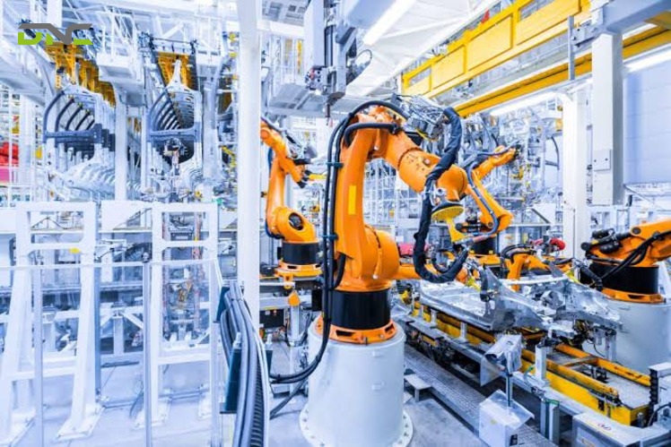
A weighing line answers all four instrumentation questions within a few metres of conveyor. A load cell senses the weight, a weighing indicator converts the signal, a PLC compares the result with set limits and a reject device acts on the pack. The table classifies each element along the four axes.
| Element | Variable | Role | Signal | Location |
| Load cell | Weight (force on a spring element) | Primary sensor | 1-3 mV/V at rated load (29.6 mV at 2.96 mV/V and 10 V) | Field, at the weighing frame |
| Weighing indicator | Weight | Transmitter | Processed output for the controller | Field enclosure or panel, set by the project |
| PLC | None | Controller | Analog input 4-20 mA or 0-10 V, or data | Control panel |
| Reject device | None | Final control element | PLC output | Field, at the conveyor |
The classification of the indicator, PLC and reject device is this article’s mapping of the loop roles in the CED and Wikipedia sources onto the instruments of a weighing line. The load cell signal comes from the site’s load-cell guides, which give 1 to 3 mV/V at rated load with a 10 V excitation. A load cell and indicator pair therefore starts from a signal of tens of millivolts, a different kind of signal from the 4-20 mA current a PLC analog card expects, and the indicator bridges that gap. The mechanism behind the millivolt output is explained in how a load cell works.
A checkweigher puts the same chain on a moving conveyor: it weighs each pack and rejects the ones outside the set limits. DNC’s engineers have specified and commissioned end-of-line packaging and weighing systems across automotive, food and beverage and glove manufacturing facilities in Malaysia. When they specify a weighing line, the first item fixed is the measurand at each station, so the signal class of every instrument is known before the PLC input cards are quoted. DNC recommends fixing that signal class at the instrument schedule, not at the wiring stage.
For Malaysian manufacturers following NIMP 2030, the New Industrial Master Plan unveiled on 1 September 2023, the same four questions return whenever a new sensor joins a line. A supplier list that stops at temperature, level and flow leaves the weighing instrument, the one the pack depends on, outside the specification.
The questions engineers ask about these instrument classes return to the same four answers, and the short versions follow.
A Weighing Line Answers All Four Questions Within a Few Metres
Frequently Asked Questions
These frequently asked questions about instrumentation types repeat the four answers in short form, covering the main groups, the loop roles, the 4-20 mA signal and the instrument that measures weight.
What are the main instrumentation types?
The main instrumentation types are the classes formed by four questions: the variable measured, the role in the loop, the signal sent and the location. By variable the common groups are pressure, temperature, level, flow and analytical, with weight as a sixth. By role they are sensor, transmitter, controller, final control element, indication and protection.
What is the difference between a sensor, a transmitter and a final control element?
A sensor is the instrument that detects the variable, a transmitter converts the sensor signal into a standard output, and a final control element acts on the process. A thermocouple detects temperature, a transmitter turns that reading into a signal such as 4-20 mA, and a control valve then moves in response to the controller. Wikipedia lists the control valve, damper, motor, solenoid valve and relay as final control elements.
Is a 4-20 mA instrument analog or digital?
A 4-20 mA instrument is analog, because the current level carries the value. HART overlays digital data on the same current loop, so the same loop carries both the analog value and digital data. Foundation Fieldbus, Profibus and Ethernet APL replace the current level with data signalling.
Which instrumentation type measures weight?
A load cell is the instrument that measures weight, as a strain-gauge spring element that delivers a millivolt signal in proportion to the force on it. A weighing indicator converts that signal for the PLC, and a checkweigher adds the reject device. DNC Automation integrates load cells, weighing indicators and checkweighers on Malaysian end-of-line lines, and you can speak with a DNC engineer to fix the signal class before the input cards are ordered.
- 0 views
- 0 Comment
Recent Comments