


Batching and Dosing Weighing System: Control, Accuracy and Specification
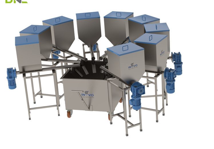
A batching and dosing weighing system meters several ingredients into one batch by weight, using feeders to move material and load cells to decide when each feeder stops. The weigh hopper, the feeder driving it, the weighing indicator reading the load cells and the recipe logic in the PLC behave as one instrument, because the accuracy of the finished batch depends on all four at once. Two control philosophies split the field: gain-in-weight, where mass is watched rising in a receiving vessel, and loss-in-weight, where mass is watched falling in the feeder itself. Both are governed internationally by OIML R 61, which classifies this equipment as an automatic gravimetric filling instrument and sets deviation limits per fill. That standard, not a vendor percentage, is what makes a batching accuracy claim checkable.
A Batching and Dosing Weighing System Controls Four Things at Once
The system controls which material moves, how fast it moves, when it stops, and what the finished batch weighed – and it records the last of those as evidence. Suppliers describe that architecture in different words: Zeppelin Systems spans it “from silo and day bin weighing to small-component dosing stations”, while Jesma describes dosing screws carrying material “from silos into our conical hopper scale, where your material is weighed and batched”. Strip the branding and the same four blocks remain.
OIML R 61-1 names those blocks precisely, which is useful when a quotation is vague. An automatic gravimetric filling instrument fills containers with a predetermined mass “from bulk (including liquid material)”, and comprises a load receptor, one or more feeding devices, and a control device built from a feed control device, a fill setting device, a final feed cut-off device and an optional correction device. Ask a supplier which physical item on their drawing is the final feed cut-off device. The answer separates integrators from resellers.
Operation runs in one of two modes: a stored recipe – ingredients each carrying a target, a tolerance and a position in the addition sequence – or a single product weighed to a preset value. Jesma states both plainly: “Weighing and batching can be carried out after recipe or single product weighing.” Recipe operation is the harder case, and it decides the control architecture.
Volumetric and Gravimetric Dosing Differ on Whether a Load Cell Closes the Loop
Volumetric dosing meters by time and rotation; gravimetric dosing meters by mass. That single distinction predicts cost, accuracy and how the system behaves when the material changes. One powder-handling manufacturer’s selection guide puts the mechanism directly: volumetric dosing “works on the principle of counting the number of revolutions and the operating time of the screw feeder”, while weight dosing includes “load cells that control the screw rotation speed and operating time”.
A volumetric feeder is therefore an open-loop device: it delivers a calibrated volume per revolution and assumes bulk density holds. Palamatic reports volumetric dosing accuracy “in the range of 3% to 5%”, calibrated by timed test – in their example, one minute at 60 rpm delivers 1.8 kg. The caveat matters more than the number: that setting “is valid only for the type of powder tested”. Change the ingredient, or its supplier, and the calibration is void.
Gravimetric dosing removes that dependency because the load cells report what actually arrived. Palamatic describes weight dosing as self-adaptive and “perfectly suited for multi-product dosing”, quoting variability below 2 % for continuous weight dosers and, in batch operation, accuracy down to 3 g. Those two figures are not the same measurand – one is a relative rate stability, the other an absolute mass per batch – and treating them as interchangeable is the first mistake in most comparison exercises.
Volumetric feeding still earns its place. Where one material runs continuously, where the tolerance is loose, and where the capital budget is the binding constraint, an open-loop screw is the correct engineering answer. Where recipes rotate, where traceability records are required, or where an ingredient is expensive enough that giveaway shows up in the monthly margin, it is not.
A Batching and Dosing Weighing System Controls Four Things at Once
Gain-in-Weight and Loss-in-Weight Place the Load Cells on Opposite Sides of the Material Flow
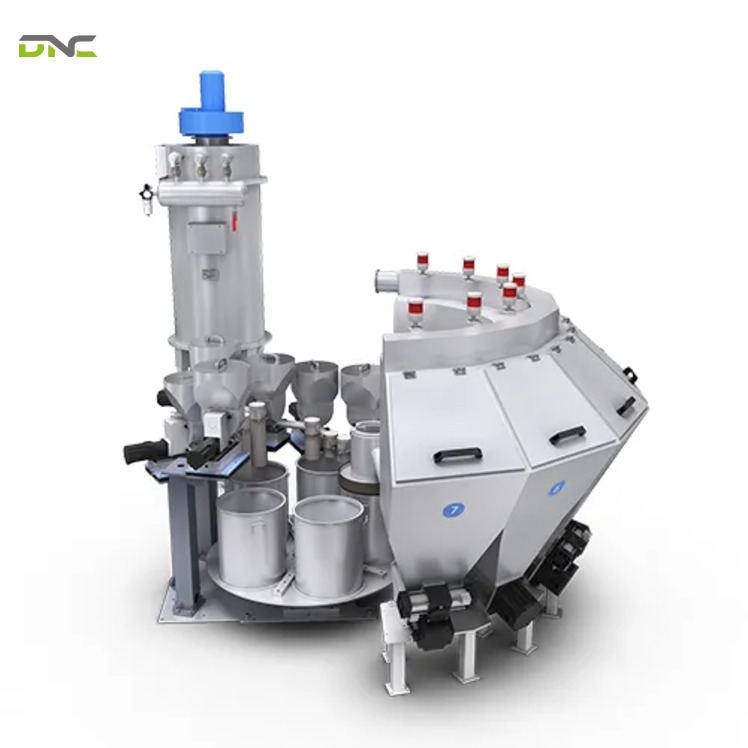
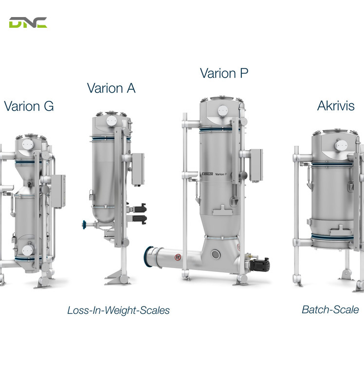
Both strategies are gravimetric; they differ in which vessel sits on the load cells. The choice governs cycle time, the number of load cells, the plant layout above the mixer and – as the refill discussion below shows – whether control is ever open-loop during production. That same selection guide states the placement rule exactly: for weight-loss operation “the load cells are located on the dosing unit”, and for weight-gain operation “the load cells are installed on the container (hopper, deconditioning pot, bags…)”. Both modes appear side by side in the Zeppelin Systems catalogue, and Mconvey builds a machine that combines them – because a real plant runs both, on different ingredients, into the same batch record.
Gain-in-weight watches a receiving hopper fill
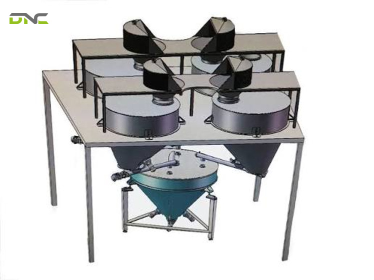
In a gain-in-weight arrangement, one weigh hopper hangs on three or four load cells and each ingredient is fed into it in sequence. The indicator tares between ingredients, so every addition is measured from a fresh zero. One weigh module can therefore serve many ingredients, which is why gain-in-weight dominates multi-ingredient recipe work: the capital sits in one accurate hopper rather than in a dozen. OIML R 61 recognises this pattern as a cumulative weighing instrument – one weighing module applying more than one weighing cycle to compose a fill.
Loss-in-weight watches a feeder empty
In a loss-in-weight arrangement, the feeder and its hopper sit on load cells together, and the control system infers delivery from the rate at which the assembly loses mass. Nothing downstream needs to be weighed, so the ingredient can be dosed straight into a moving process – an extruder throat, a continuous mixer, a coating line. OIML R 61 classifies fills determined by controlling the output feed from the weigh hopper as subtractive weighing instruments.
The refill window is the one moment a gravimetric feeder is not gravimetric
The refill window breaks gravimetric control, because during refill the feeder’s load cells cannot separate incoming mass from outgoing dosed mass. Palamatic is explicit about the consequence: the re-feed time “must be extremely short (ration 1/10)”, and “during the re-feeding phase, the weight dispenser functions as a volumetric dispenser”. For roughly one tenth of the duty cycle, then, the feeder falls back to speed × time and inherits volumetric accuracy – including the 3 %–5 % band and the material sensitivity that came with it. A loss-in-weight specification that does not state refill frequency, refill duration and hopper working volume has left its worst-case accuracy undefined.
Hybrid machines run both on one frame
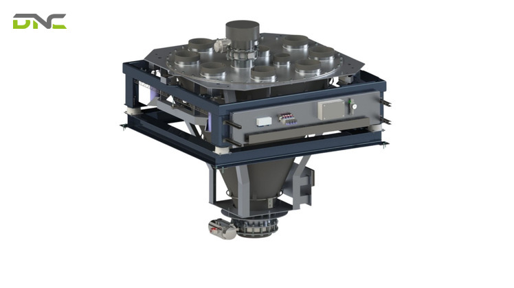
Hybrid machines run both modes on one frame: Mconvey’s multi-component weigher “adopts a dosing device that combines ‘loss-in-weight’ and ‘gain-in-weight'” in a modular frame of 2 to 12 dosing groups. The logic is straightforward: majors go gain-in-weight into a shared hopper, while an ingredient that must arrive continuously runs loss-in-weight on its own module. Specify the split by ingredient behaviour, not by machine catalogue.

Hybrid machines run both on one frame
Every Fill Ends With Material Still in the Air
Every fill finishes with material still in the air. The feeder stops short of the target, and what it already released keeps arriving. Palamatic describes the resulting three-phase cycle for both screw and vibrating feeders: high speed dosing, then low speed dosing at 10 % of high speed, then the fall tail. The first phase buys throughput, the second buys resolution, the third is the error the control system has to predict.
OIML R 61 anticipates the same physics from the regulatory side. The final feed cut-off device is defined as the device that “controls the cut-off of the final feed so that the average value of the mass of the fills corresponds to the preset value”, and §5.5 permits it to “include a device which corrects for the residual material feed into the weighing module after cut-off”. The standard does not ask designers to eliminate in-flight material. It asks them to correct for it, and to make the device that does so clearly distinguishable on the machine.
In-flight mass is the product of feed rate and dead time, and dead time is not free. From DNC’s weighing specifications, an industrial weighing indicator converts at 10 to 100 conversions per second – one reading every 10 to 100 ms – and passes the result through two digital filters in series with a cutoff between 0.7 and 11 Hz. Every millisecond of conversion interval and filter settling is a millisecond during which the feeder is still running on a stale reading. Dribbling at 10 % of high speed cuts the in-flight mass by the same factor, which is the entire reason the dribble phase exists.
That chain has a practical consequence when a line is pushed for throughput. Shortening the dribble phase to gain cycle time increases in-flight mass in direct proportion, and no amount of load cell accuracy recovers it. When our engineers commission a batching line, feed-rate profiling comes before any discussion of a higher-resolution load cell – the cut-off is almost always the dominant error term, and it costs nothing to re-tune.
Every Fill Ends With Material Still in the Air
Summary – the Dosing Loop in Four Decisions
Four decisions have now been made, and together they define the control loop. Whether a load cell sits in the loop separates volumetric from gravimetric metering, and with it the 3 %–5 % band from the sub-2 % band the same guide reports. Where that load cell sits separates gain-in-weight from loss-in-weight, and decides whether refill periods run open-loop. How the feed rate steps down – high speed, dribble at 10 %, fall tail – sets the in-flight mass at cut-off. And how fast the indicator converts, at 10 to 100 conversions per second, bounds how quickly the cut-off command can act on a real reading. Everything below is either a consequence of these four or a check on them.
Ingredient Mass Tiers Split One Recipe Across Several Scales
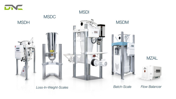
Ingredient mass tiers exist because a recipe spanning grams and tonnes cannot be weighed on one scale, so ingredients are grouped by mass and each tier gets its own weigh module. One Malaysian process automation supplier lists micro, minor and major ingredient dosing, weighing and batching systems as three distinct product lines. Jesma sizes a scale family the same way but names the tiers differently: nano covers JesBatch 2–30 kg, micro covers 50–200 kg, and medi-/macro covers 400–1000 kg.
Those two vocabularies do not align, and the gap is a real procurement hazard. Jesma’s “micro” band starts at 50 kg – a mass most process engineers would call a minor ingredient, and one the micro/minor/major scheme places in its minor line. Two quotations that both say “micro dosing station” can describe machines an order of magnitude apart in capacity. Ask for the capacity range in kilograms and the scale interval in grams; ignore the tier name entirely.
Jesma also publishes what a tier actually buys in accuracy. The JesBatch-400 carries a static capacity of 200–400 kg at ±100 g, the JesBatch-600 covers 200–600 kg at ±200 g, and the JesBatch-1000 covers 200–1000 kg (0.2–1 tonne / 441–2,205 lb) at ±250 g. Expressed against capacity – arithmetic on their published pairs, not a separate finding – that is roughly 0.025 %, 0.033 % and 0.025 % respectively. The accuracy scales with the scale, which is precisely why splitting a recipe across tiers recovers precision that a single large hopper throws away.
| Tier position | Micro / minor / major scheme | Jesma capacity band | Typical recipe role |
| Smallest | Micro ingredients | Nano, 2–30 kg | Actives, colours, vitamins |
| Middle | Minor ingredients | Micro, 50–200 kg | Additives, functional powders |
| Largest | Major ingredients | Medi-/macro, 400–1000 kg | Base powders, fillers, carriers |
Ingredient Mass Tiers Split One Recipe Across Several Scales
Feeder Choice Follows Powder Behaviour Before Throughput
The material decides the feeder; the throughput only decides its size. The selection logic rests on four factors – the precision of the metering, the rate of progress, whether the application is batch or continuous, and the type of powder in terms of grain size, density and flowability. Zeppelin frames the same variable as free-flowing versus difficult-to-flow bulk materials.
Two feeder families cover most of the field, and they include the screw type and the vibrating type, dividing on fragility rather than on flow rate:
- Screw feederssuit fine, dusty, variable-density powders of medium flowability, with screw profile selected against grain size and density. Cocoa powders, spice mixes and texturisers are the duties named.
- Vibrating feederssuit fragile or delicate ingredients – glass fibres, dried fruit, abrasive materials, coarse granules – and run the same three-phase high-speed, low-speed, fall-tail cycle as the screw.
Liquids belong in the same specification rather than in a separate project. Zeppelin Systems doses “liquids and temperature-controlled masses” by volumetric or gravimetric measuring systems, and its weighing range covers “granular as well as difficult-flowing powdered bulk materials and liquids” – the same instrument class OIML R 61 already includes. Where a recipe mixes powders and liquids, splitting them across two control systems creates two batch records for one batch, which is the failure the recipe layer exists to prevent.
Where precision is not the binding constraint, cheaper metering elements exist, and Palamatic quantifies what they give up. A butterfly or knife gate valve driven by a 4–20 mA proportional actuator handles very high flow rates at medium accuracy. A rotary valve suits fine powders under hygiene constraints, with accuracy “in the range of ½ litre”. A rotary airlock valve for continuous fine-powder duty is quoted at around one litre. Those figures are volumetric – litres, not grams – which is a reminder of what changes when the load cell leaves the loop.
Feeder selection also has to survive the layout it lands in. The transfer equipment between silo, feeder and mixer belongs in the accuracy budget, which is why DNC specifies it alongside the weighing hardware in the same package as our Conveyor System Solutions for Factory Automation – a hopper fed by an unstable upstream flow chases its own setpoint no matter how good the load cells are.
An Accuracy Figure Means Nothing Without a Class and a Fill Band
Here is the specification failure that runs through almost every published page on this equipment: a percentage with no class and no fill mass is not an accuracy specification. OIML R 61-1 sets maximum permissible deviation per fill in a table that is not a flat percentage at all. It alternates between percentage bands and fixed-gram bands as fill mass rises.
| Fill mass F (g) | mpd, class X(1) – initial verification | In-service |
| F ≤ 50 | 7.2 % of F | 9 % of F |
| 50 < F ≤ 100 | 3.6 g | 4.5 g |
| 100 < F ≤ 200 | 3.6 % of F | 4.5 % of F |
| 200 < F ≤ 300 | 7.2 g | 9 g |
| 300 < F ≤ 500 | 2.4 % of F | 3 % of F |
| 500 < F ≤ 1 000 | 12 g | 15 g |
| 1 000 < F ≤ 10 000 | 1.2 % of F | 1.5 % of F |
| 10 000 < F ≤ 15 000 | 120 g | 150 g |
| F > 15 000 | 0.8 % of F | 1 % of F |
An Accuracy Figure Means Nothing Without a Class and a Fill Band
Two properties of that table repay study. In-service limits are exactly 1.25 times the initial-verification limits across every band, so a machine verified at the tolerance limit has 25 % of headroom before it falls out of compliance in service. And the whole table scales: the manufacturer declares an accuracy class X(x), where the class designation factor x “shall be ≤ 2 and in the form 1 × 10ᵏ, 2 × 10ᵏ, 5 × 10ᵏ”. Class X(0.2) is five times tighter than X(1). Class X(2) is twice as loose. The same physical machine can be marked either way.
The standard tightens two further limits to a quarter of the deviation limit. The maximum permissible error for influence factor tests is 0.25 × mpd in-service, and the maximum permissible preset value error – the gap between what the operator asked for and the average of what the machine delivered – must also stay within 0.25 mpd in-service.
Set the vendor figures from this SERP against that frame and the problem becomes visible. One supplier quotes 3 %–5 % (volumetric, relative to setpoint), under 2 % (continuous gravimetric rate variability) and 3 g (per batch, absolute). Jesma quotes ±100 g to ±250 g (absolute, per scale). Mconvey quotes ±1 % per hour, which is a drift rate across a shift, and states its throughput basis as a reference material of 0.65 g/cm³ (650 kg/m³) bulk density, angle of repose ≤ 40° and particle size ≤ 3000 mesh – adding that “the real feeding rate must be determined through testing with the specific material in use”. Four measurands, one word. None of them is comparable to another, and none is verifiable without the class and the fill band.
Our position on this is not subtle: ask for the class designation, the fill mass range it was declared over, and the material the type evaluation used. A supplier who can produce all three is quoting an instrument. A supplier who offers a single percentage is quoting a brochure.
Rated Minimum Fill Sets the Floor Nobody Quotes
Rated minimum fill sets the floor beneath every accuracy claim. Equipment pages state a maximum capacity and stop there; none of them states the smallest fill the machine still certifies – the number that decides the whole design of a micro-ingredient station. OIML R 61-1 calls it the rated minimum fill, Minfill, and it applies the deviation limits only to fills at or above it. Below Minfill, the machine is not out of tolerance; it is simply outside the scope of its own accuracy claim.
Minfill is bounded by the scale interval d and the accuracy class, in grams:
| d (g) | X(0.2) | X(0.5) | X(1) | X(2) |
| 0.5 | 28.0 | 11.0 | 5.5 | 3.0 |
| 1 | 111 | 22 | 11 | 6 |
| 2 | 334 | 44 | 22 | 12 |
| 5 | 1 665 | 335 | 110 | 30 |
| 10 | 3 330 | 1 330 | 330 | 110 |
| 20 | 6 660 | 2 660 | 1 340 | 340 |
| 50 | 25 000 | 6 650 | 3 350 | 1 650 |
| 100 | 50 000 | 20 000 | 6 700 | 3 300 |
| 200 | 100 000 | 40 000 | 20 000 | 6 600 |
| ≥ 500 | 500 d | 200 d | 100 d | 50 d |
Read one row and the design constraint appears. A weigh hopper with a 50 g scale interval cannot certify a 1 kg micro-ingredient addition at class X(1), because Table 3 puts the floor at 3 350 g (3.35 kg / 7.4 lb). The hopper is not faulty. It is the wrong hopper for that ingredient, and the only fixes are a finer scale interval, a looser class, or a separate micro station – which is exactly why ingredient tiers exist.
The standard also lists what pushes Minfill up: temperature effect on the no-load indication, zero-setting accuracy, disturbances, warm-up time, the product itself, and the scale interval. Four of those six are environmental. A weigh hopper mounted beside a vibrating screen or in an unconditioned Malaysian production hall carries a higher effective floor than the same hopper on a test bench, which is a commissioning argument rather than a purchasing one.
Rated Minimum Fill Sets the Floor Nobody Quotes
Summary – What Turns an Accuracy Claim Into a Specification
Turning an accuracy claim into a specification takes three parts, and a bare vendor percentage carries none of them. The first is the accuracy class X(x), which scales the whole deviation table by a factor of 0.2, 0.5, 1 or 2. The second is the fill mass band, because the maximum permissible deviation is a staircase – 1.2 % of fill between 1 000 g and 10 000 g, but a flat 12 g just below that range. The third is the rated minimum fill, which turns the scale interval into a hard floor: at a 50 g scale interval and class X(1), no fill under 3 350 g (3.35 kg) is covered at all. Class, band, floor. Ask for all three.
Mechanical Isolation Decides Whether the Weight Reading Is Real
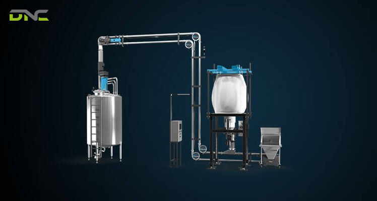
Mechanical isolation decides whether the weight reading is real. A load cell measures every force reaching the weigh module, not only the material inside it. Rigid pipework, conduit, dust extraction ducting and a stiff discharge spout all inject force into a hopper that is supposed to be free-hanging, and no calibration removes it. The same powder-handling guide flags this failure mode: “It is essential to be careful with weighing interference. For example, the use of specific sleeves is necessary to ensure the quality of the dosage and avoid constraints on the weight sensors.”
OIML R 61 adds the discharge side of the problem. The load receptor and feed and discharge devices “shall be designed to ensure that residual material retained after each discharge is negligible”, and subtractive instruments must ensure residual material retained at the discharge gate is negligible too. Material that clings to a hopper wall reports as delivered mass on this batch and as tare error on the next.
Three checks catch most of it before commissioning. Confirm that every connection into and out of the weigh module is a flexible sleeve rather than a bolted flange. Confirm that the discharge geometry empties completely for the worst-flowing ingredient in the recipe, not the best. Confirm that the load cell mounts allow the hopper to move in the weighing direction only. These are drawing-review items, and they cost nothing at that stage – after steelwork is installed, the same three findings become site modifications.
Mechanical Isolation Decides Whether the Weight Reading Is Real
Specifying the System for a Malaysian Plant
DNC Automation has engineered and commissioned weighing and load cell systems across Malaysian food and beverage, edible oils, glove manufacturing and automotive facilities for 20 years, with 35 in-house engineers and an ISO 9001:2015 quality system behind the design work. Batching and dosing sits on the same instrumentation stack as our JY and DNX-WR weighing series and our checkweigher integration work – the difference is that the control decision happens before the product exists rather than after.
The specification sequence our engineers follow starts with the recipe rather than the machine, and it includes six ordered steps:
- Tabulate the recipe by ingredient mass, then group into tiers. The spread between the largest and smallest addition decides how many weigh modules the line needs.
- Fix the accuracy class and fill band per tier, using the mpd and Minfill tables above. This is the step that eliminates most catalogue options honestly.
- Assign a dosing mode per ingredient– gain-in-weight into a shared hopper for anything sequential, loss-in-weight for anything that must arrive continuously.
- Profile the feed rate and dribble ratioagainst the cut-off dead time, before selecting load cell capacity.
- Characterise every powderfor grain size, bulk density and flowability, and test with the actual material rather than a reference powder.
- Review the mechanical isolationon drawings: flexible sleeves, discharge geometry, load cell mounting direction.
Recipe control and batch records belong in that same specification. Our Smart Manufacturing & Industry 4.0 Solutions Malaysia practice covers the PLC and SCADA layer that stores formulas, enforces the addition sequence and retains per-batch weight records – what turns a set of accurate hoppers into a traceable process. Where the finished pack is verified downstream, our Machine Vision & Automated Inspection Systems close the loop between what was dosed and what shipped.
For Malaysian manufacturers, the timing argument is straightforward. NIMP 2030 incentives favour plants that automate and instrument their processes inside this decade, and batching is one of the few places where the investment produces both a compliance record and a direct material saving – every gram of giveaway eliminated on a high-value ingredient is recovered on every batch, permanently.
Specifying the System for a Malaysian Plant
Frequently Asked Questions
These are the questions plant teams ask most frequently when they first scope a multi-ingredient weighing line, and each answer points back to the section that covers it in full.
What is a batching and dosing weighing system?
A batching and dosing weighing system is a set of feeders, weigh modules and recipe logic that meters several ingredients into one batch by mass rather than by volume. Load cells under the weigh hopper or under the feeder tell the control system when each ingredient has reached its target, and the system records what was actually delivered for each batch.
What is the difference between batching and dosing?
The difference is one of scope: dosing is the delivery of one material at a controlled rate or to a controlled quantity, while batching is the composition of a complete recipe from several dosed ingredients in a defined sequence. A batching system contains multiple dosing devices; a dosing device on its own is not a batching system.
Is gain-in-weight or loss-in-weight more accurate?
Neither is inherently more accurate – they fail differently. Gain-in-weight puts the whole recipe on one well-specified hopper and tares between ingredients. Loss-in-weight delivers continuously but runs open-loop during refill, which its manufacturers describe as functioning as a volumetric dispenser for that period. Judge them on duty cycle, not on a headline figure.
How accurate can a batching and dosing weighing system be?
How accurate a batching and dosing weighing system is depends on fill mass, not on a single percentage. Under OIML R 61-1, a class X(1) instrument is held to 1.2 % of fill for fills between 1 kg and 10 kg at initial verification, but to a fixed 12 g between 500 g and 1 kg, and to 7.2 % for fills of 50 g or less. Any accuracy claim needs a class designation and a fill band to be checkable.
Why does a feeder slow down before reaching the target weight?
Because material released before the feeder stops still has to land. The feed runs a three-phase cycle – high speed, low speed at 10 % of high speed, then the fall tail. The slow phase reduces how much material is in flight at cut-off, and OIML R 61 allows the final feed cut-off device to carry a correction for the residue that arrives anyway.
Can an existing batching line be upgraded without replacing the hoppers?
An existing batching line is often upgraded without replacing the hoppers. Where hopper capacity, scale interval and mechanical isolation already suit the recipe, the work sits in the load cells, the weighing indicator and the recipe control layer. Where the recipe now spans a wider ingredient mass range than the original design, the rated minimum fill usually forces an additional weigh module rather than a controls retrofit.
If your facility is specifying a batching and dosing weighing system – or trying to work out why an existing line drifts on some ingredients and not others – DNC’s engineers can specify the class, the tier split and the feeder configuration against your actual recipe and powder data. Talk to our engineers.
- 30 views
- 0 Comment
Recent Comments