


CIP Cleaning in Filling Lines: Valves, Not Just Flow
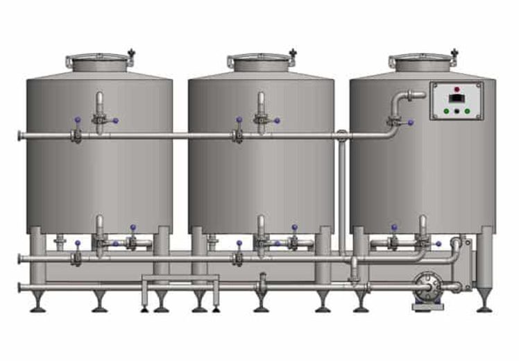
CIP cleaning in filling lines — clean-in-place cleaning, not the firearms proof standard that shares the abbreviation — circulates water, detergent and heat through a closed interior circuit without opening the machine, which is the definition the process industry already applies to tanks and pipelines. A filling machine breaks the circuit topology that definition assumes. Instead of one continuous circuit, a rotary filler repeats a small circuit dozens of times over: each filling element carries a liquid channel fed from the annular bowl, a liquid valve, a return gas tube and two gas-path control valves, and every one of those has to be commanded open before solution reaches the surface behind it. A rinse cap seals each head so that the circuit closes at all. Caustic, acid and peracetic sanitiser still do the chemical work, and a changeover matrix still sets how often the work happens. On a filler, coverage is a sequencing outcome rather than a flow-rate outcome.
CIP Cleaning in a Filling Line Circulates Solution Through Paths, Not Through Volume
CIP cleaning in a filling line moves water, chemical and heat through the closed interior of the equipment without dismantling it and with little or no operator involvement. Rheonics quotes the process-industry definition of clean-in-place in full: “the cleaning of complete items of plant or pipeline circuits without dismantling or opening of the equipment, and with little or no manual involvement on the part of the operator. The process involves the jetting or spraying of surfaces or circulation of cleaning solutions through the plant under conditions of increased turbulence and flow velocity.” Laminar states the same boundary more plainly, as “a method of cleaning interior surfaces of pipes, vessels, tanks, and equipment without disassembly, using water, chemicals, heat, and flow to remove product residue and contaminants.”
In process-plant terms, the design question that follows is delivery. IC Filling Systems sorts the answer by soil load and geometry into three principles: highly turbulent, high flow-rate solution for pipe circuits and some filled equipment; a low-energy spray that fully wets the surface of lightly soiled vessels behind a static sprayball; and a high-energy impinging spray from a dynamic device for heavily soiled or large-diameter vessels. Temperature and detergent then raise the effectiveness of whichever delivery method the geometry called for.
Each of those three principles assumes the solution can reach the surface once it is moving. That assumption holds for a pipe, holds for a tank, and stops holding at the filler. A filling machine’s wetted interior is not one circuit but the same small circuit repeated at every head, and the surfaces inside each repeat sit behind valves that are shut until something commands them open. Delivery is settled; access is not. The unit that decides access is the filling element, and an automated bottle filling line carries dozens of them on a single rotor.
CIP Cleaning in a Filling Line Circulates Solution Through Paths, Not Through Volume
The Filling Element Is the Unit a Filling-Line CIP Has to Clean
The filling element is the unit a filling-line CIP has to clean, and a single filler carries dozens of them, each with its own valves and its own flow paths. Laminar reaches the same conclusion from the plant side and states it in one passage: “Filling stations are the most complex CIP targets. A single filler may have dozens of valves, manifolds, and flow paths—each of which needs to be flushed during cleaning. CIP programs for fillers typically include multiple sub-steps that cycle through different flow paths within a single cleaning phase. If you’re troubleshooting a filler CIP, confirm that all sub-steps are actually running; incomplete path coverage is a common cause of validation failures.”
Those 56 words are the whole of it. They sit inside a 4,850-word guide, alongside longer treatments of tanks, piping, valves, hoses and heat exchangers, and they are the deepest filler-specific passage published on this search result page. What a flow path on a filler physically is, why there are dozens, what closes the circuit at a head, and what drives the sub-step order — none of that is answered anywhere the reader can follow it. The one document that does answer it is a 1996 German patent on clean-in-place cleaning of filling machines, DE19636805A1, later published as EP0829450B1 and classified under B67C 3/001, “Cleaning of filling devices”. Its vocabulary is where the rest of this section comes from.
Liquid Path and Gas Path Are Two Separate Circuits Inside One Filling Element
The liquid path and the gas path are two separate product-contact circuits inside one filling element, and CIP media have to flow through both of them in a closed circulation. The patent opens on exactly that point, describing how the gas and liquid paths are cleaned “by operating the valves there, namely the liquid valves in the liquid paths or channels and the control valves in the gas paths, so opened and closed that the gas and liquid paths to be cleaned in the desired way [can be] flowed through from the liquid cleaning media in a closed circulation.”
From a machine-anatomy point of view, the two circuits use different components. The table below lists what the patent names on one filling element of a rotary counter-pressure machine.
| Circuit | Components named in DE19636805A1 |
| Liquid path | Annular bowl forming the ring-shaped interior that holds the product; liquid channel inside the element housing; valve body seated in that channel to form the liquid valve; annular outlet opening at the underside of the housing; centring tulip with a seal |
| Gas path | Return gas tube running coaxially with the vertical filling-element axis and projecting through the annular outlet; the span gas space above the product in the annular bowl; the return gas collecting duct; two pneumatically actuated gas-path control valves that govern which of those connects to which |
Command runs through a third layer that belongs to neither circuit and sits where a smart manufacturing control platform can read it. The pneumatic actuator that lifts the return gas tube and valve body, and both gas-path control valves, are each given their own electrically actuated pneumatic valve, and those valves across every filling element on the machine answer to one central computer or microprocessor control device running a stored programme. Three commanded valves per head is the arithmetic that turns “dozens of valves” into a real number: twelve heads is thirty-six commands, forty heads is a hundred and twenty. A tank has one product-contact network and a filler has two of them per head, multiplied by the head count. Neither network is reachable until the circuit is closed at the bottom.
The Rinse Cap Closes the Filling Element’s Circuit
A rinse cap closes the filling element’s circuit by sealing the annular outlet that otherwise discharges into open air. The patent states this as a precondition rather than an option: “a prerequisite for this CIP cleaning is, of course, that all filling elements are sealed by the rinsing container or rinsing sleeves or CIP caps.” The same component appears under three names in that sentence — rinse container, rinse sleeve, CIP cap — because the German original uses three, and the part is drawn in bottle form in the patent figures while the text notes it can take any other suitable shape.
The reason the cap is structural rather than procedural sits in the outlet arrangement described above. A filling element discharges downward through an annular outlet with the return gas tube standing in the middle of it, into a bottle that is not there during cleaning. Without a cap under the head there is no return route, so solution leaving the liquid valve exits to atmosphere and never comes back to the skid. The closed circulation that the definition of CIP depends on is not partly satisfied at that head — it is not satisfied at all.
One badly seated cap therefore converts a closed circuit into an open drain at a single element while every other head behaves normally. That is the same defect the industry already names as incomplete path coverage, arriving from the mechanical side instead of the programming side. Whether a path stays dirty because a cap was missed or because a valve never switched, the cleaning record looks identical, and what determined the switching in the first place is how the machine drives its valves.
Rotor Motion Decides How a Filler Sequences Its CIP Valves
Rotor motion decides how a filler sequences its CIP valves, because on a mechanically actuated machine the valve command is rotor angle. The patent describes the older architecture directly: on mechanical filling machines the actuation required to open and close the gas and liquid paths “takes place via curves and shift linkages in certain angular ranges of the rotary movement of the rotor.” Cams and shift linkages convert angular position into valve position. A rotor standing still is a filler whose valves cannot change state.
That constraint produced the convention. “In all previously known filling machines,” the same document records, “CIP cleaning is carried out with reduced speed of the filling machine running, i.e. with rotating rotor.” Early electronic fillers then inherited the convention without inheriting the constraint — an opening and closing angle for CIP was defined in software, and the rotor still turned while the cleaning ran.
The method the patent claims removes the motion and keeps the angle. CIP runs “with a standing, i.e. not rotating rotor by appropriate actuation of the valves of the filling elements … through the electronic control”, and in the preferred embodiment the opening and closing of those valves “from filler element to filler element takes place at different times or out of phase, so that when the rotor is stationary, circumferential opening and closing angles result in a predetermined circumferential direction.” Stagger the commands head to head and the open sector travels around the ring. An opening angle that travels around a rotor standing still is doing the job that rotation used to do.
The claimed benefit is not speed. It is flow: because only part of the ring is open at any instant, “all filling elements or their gas and liquid paths are nevertheless intensively treated with these cleaning media, inter alia with the lowest possible volume flows of the cleaning media used for CIP cleaning.” Reading that against the head arithmetic gives the engineering reason — opening every head at once would demand pump capacity for every head in parallel, while a travelling wave demands capacity for the open sector only. That reading is this site’s inference from the two statements rather than text lifted from the document. Sequencing, in either architecture, is what routes the solution; the solution itself is mixed elsewhere, on the same recipe the rest of the plant uses.
Rotor Motion Decides How a Filler Sequences Its CIP Valves
CIP Chemistry on a Filling Line Follows the Plant’s Caustic, Acid and Sanitiser Order
CIP chemistry on a filling line runs the same three solutions as the rest of the plant: caustic for organic soil, acid for mineral scale, and a sanitiser for the microbial kill. In terms of chemistry the filler is not a special case, which is why this section matches the published plant practice rather than departing from it. The stages, their working strengths and their temperatures are set out below as each source publishes them.
| Stage | Function | Strength and temperature as published | Source |
| Pre-rinse | Removes bulk residue with water before any chemical enters the circuit | Hot water; reclaimed final-rinse water is usable | Laminar; IC Filling Systems |
| Caustic wash | Breaks down fats, proteins, starches and oils | Sodium hydroxide at 1-4%, run hot at 65-80 °C (149-176 °F) per Laminar; 1.5% caustic soda in water at 80 °C (176 °F) per IC Filling Systems, with 120 °C (248 °F) pressurised steam given as the alternative | Laminar; IC Filling Systems |
| Intermediate rinse | Clears caustic before acid enters, since residual caustic neutralises the acid step | Water | Laminar |
| Acid wash | Removes mineral deposits and the scale that repeated caustic washing leaves behind | 0.5-1.5%, ambient or warm; nitric acid most common in food and beverage, phosphoric where nitric is too harsh, citric as the lower-impact option that is “less effective on heavy scale” | Laminar |
| Sanitiser | Kills the bacteria, yeast, mould and viruses that survive the wash stages | Peracetic acid run cold at 100-200 ppm, contact time a few minutes; or hot water alone at 82 °C (180 °F) and above, at a higher energy cost. IC Filling Systems runs a 1.5% peracetic solution cold, or steam at 120 °C | Laminar; IC Filling Systems |
Caustic precedes acid for a reason the sources agree on. High pH leaves calcium carbonate on the wetted surfaces over time, so the acid stage does double duty — it removes the soils caustic cannot touch, and it descales what caustic deposited. Reversing the pair would descale first and then re-scale.
The two published caustic strengths disagree, and the disagreement is worth carrying openly rather than averaging away. Laminar gives 1-4% as the working band and notes that chemical arrives at 50% NaOH concentration in IBC tanks or drums before dilution; IC Filling Systems states 1.5% for its own filling-machine cycle. The second figure sits inside the first band, so both hold — one is a range across an industry, the other is one supplier’s setpoint on one class of machine.
Sanitiser strength is quoted in a unit that suits neither of the wash stages: the peracetic figure above is 200 ppm (0.02% / 200 mg per litre) at the top of its band, against a caustic band expressed as a percentage of a 50% concentrate. Strength is held rather than set once. Dosing is controlled by conductivity, with the system monitoring the solution tank or the return loop and adding chemical to keep a setpoint that Laminar puts commonly at 30-50 mS/cm for caustic. Inline dosing introduces a lag between the chemical entering the line and the return sensor seeing it, which produces overshoot and a recognisable data signature: conductivity spiking well above setpoint before settling back. What changes between plants is not the chemistry but how many of these stages the recipe strings together.
Step Count Names the CIP Cycle, and the Intermediate Rinse Is What It Buys
Step count names the CIP cycle, and the step that separates a three-step cycle from a five-step cycle is the intermediate rinse rather than a second dose of cleaning power. The four standard programmes are described below in the order of increasing chemical stages.
- One-stepruns a hot water flush alone, and appears where hygiene requirements sit below food and beverage levels. Cold water alone does not qualify — Laminar classifies a cold flush as a changeover rather than a CIP.
- Three-steprinses with water, circulates one chemical, and rinses again. It is the fastest chemical cycle and suits moderate soil loads with compatible products either side of the changeover.
- Five-stepinserts an intermediate rinse and a second chemical: rinse, chemical, intermediate rinse, chemical, final rinse. Caustic and acid cannot meet, so the middle rinse is what makes running both possible in one cycle.
- Seven-stepadds a further intermediate rinse and a dedicated sanitiser stage, giving rinse, chemical, rinse, chemical, rinse, sanitiser, rinse. Dairy and pharmaceutical lines run it because a documented microbial kill is what auditors ask to see.
Clean-in-place cycle time follows the count without tracking it neatly. Laminar puts standard three-step and five-step cycles at 30 minutes to 2 hours, seven-step cycles in dairy and pharmaceutical plants at 60-90 minutes, and extended cycles in flavour and fragrance production at 5-7 hours where residues are potent enough to justify the wait. A seven-step programme is not automatically the longest one on site. What the count reliably predicts is the number of places a cycle has to be sequenced correctly, and on a filler that number is multiplied by the head count.
Summary: What the Filler Adds to a Plant CIP Programme
To draw together what the first four sections establish: CIP cleans a closed interior circuit without disassembly, and the plant-side design question is how to deliver solution to a surface. A filling machine changes that question, because its interior is one small circuit repeated at every filling element, and each element hides its wetted surfaces behind a liquid valve and two gas-path control valves that must be commanded open. A rinse cap under each head is what closes the circuit at all. How those valves get commanded depends on whether the machine is cam-driven or electronically driven, since a cam ties the valve command to rotor angle. Chemistry itself is plant-generic — caustic, acid, sanitiser, in that order, separated by rinses — and the step count records how many stages the recipe strings together. The filler contributes none of the chemistry and all of the sequencing.
What the Filler Adds to a Plant CIP Programme
Incomplete Path Coverage Fails a Filler CIP, and Stronger Chemistry Does Not Fix It
Incomplete path coverage fails a filler CIP, and it presents as a hygiene result rather than as a machine alarm. From a troubleshooting point of view that is the whole difficulty. Laminar names the failure mode and its diagnostic step in one instruction — “confirm that all sub-steps are actually running; incomplete path coverage is a common cause of validation failures” — but a sub-step that did not run produces no fault code, no pressure drop and no conductivity excursion. The cycle completes. The swab comes back positive somewhere downstream of it.
What the operator sees, then, is a cleaning result, and cleaning results have an obvious set of levers. Raise the caustic concentration. Extend the contact time. Move from a three-step recipe to a five-step. Each of those is a rational response to a soil that survived the wash, and each of them is aimed at the wrong variable, because a sub-step is a valve state rather than a flow rate. Chemistry cannot reach a valve that never opened. A gas path whose control valve stayed shut is exactly as dirty after a caustic wash at 80 °C (176 °F / 353 K) as it was after the milder wash that preceded it.
Escalation is not free either. A longer cycle consumes more chemical, more water and more heat, and it lengthens the stop; a stronger caustic accelerates the calcium carbonate deposition that then demands more acid. Rheonics describes where this ends as an operator behaviour rather than a technical setting: “with the risk of contamination at the forefront of most operators’ minds, the tendency of the CIP operator is to overcompensate with increased cleaning time.” Laminar’s version of the same reflex is that plants keep “running the CIP program that was set up a decade ago, designed for worst-case conditions.”
The correct instrument is the sub-step list, not the recipe. When DNC’s engineers specify a filling line, the CIP question asked first is how many discrete flow paths the filler carries and how the control programme addresses each of them, because that count is what a validation exercise has to walk through. Confirming which paths were actually switched turns an unexplained hygiene result into a bounded search. It also reframes what the cleaning stop costs, since a filler that is being sequenced is a filler that is standing still.
A Stationary Filler Turns the Cleaning Window Into Shared Time
A stationary filler turns the cleaning window into shared time, because the machine being cleaned is simultaneously available for work that does not touch the circuit. Viewed from a production-planning point of view, a filler CIP cycle contradicts how every other source on this subject frames cleaning time. Rheonics puts the standard view in one line — “any cleaning time is downtime – the equipment is not productive” — and Laminar quantifies the standard remedy, noting that a facility running 10 CIPs per day and saving 2 minutes per step across 7 steps reclaims over 2 hours of production time daily. Both treat the cycle as a cost to be shortened.
The patent that describes stationary-rotor clean-in-place treats the same duration as an opportunity, and states it as a claimed advantage of the method. During CIP cleaning, “for which a relatively long time is required (sometimes up to more than two hours), other work on the standing filling machine can [be done], for example retrofitting and maintenance work, provided that this work does not interfere with the CIP cleaning.” It then names the specific job: converting the machine to a different container or bottle size by rebuilding or exchanging the bottle guide elements. Container format is what changes here, so the same argument reaches a drum filling system whose change parts differ from a bottle line’s without differing in when they can be fitted. The changeover time it gives for that work is 30 to 60 minutes, and the document states it “can easily be accommodated in the time required for CIP cleaning.”
Both figures belong to that document’s own embodiment and are quoted as such, not as an industry norm. The mechanism behind them generalises more readily than the numbers do. The filler does not stand alone: bottles reach the rotor over the infeed of the conveyor system automation and an inlet star, pass by a transfer star to a closing machine such as a crown-cap closer, and leave by an outlet star to a discharge conveyor, with guide elements at each star — and the filler rotor, the closer rotor and the stars are driven by a common drive as one machine block. Stop the rotor for cleaning and the closer and the stars stop with it, which is precisely what makes their guide elements accessible.
Plant practice already contains the manoeuvre under a different name, since clean-in-place and clean-out-of-place are routinely scheduled against each other. Laminar describes how clean-out-of-place work is scheduled around a cleaning cycle rather than after it: the operator “first disassembles the components on the line that requires COP and preps the line for CIP. The line can then undergo CIP and its disassembled components can undergo COP at the same time. After both CIP and COP is complete, the line can be reassembled to begin production.” The same page frames the resulting question as a bottleneck problem — which of the two processes is holding the other up, and how much hidden time sits in disassembly and reassembly. Applying that scheduling logic to a filler’s change parts instead of a line’s fittings is a small step, and the parts overlap: gaskets, seals and the rinse caps themselves are all COP items.
The practical sequence for a filler stop follows from the two sources read together and looks like this.
- Strip the COP items — seals, gaskets, small fittings — and fit the rinse caps to every filling element.
- Start the CIP programme with the rotor stationary, confirming the sub-step list addresses every liquid path and every gas path.
- Run the format changeover in parallel: exchange the guide elements at the filler, the closer and the stars while the circuit is closed and circulating.
- Run COP on the stripped parts concurrently, in a wash cabinet or by hand.
- Reassemble, seat the new format parts, remove the caps, and release the line.
Hygiene managers read a cleaning cycle as a duration to be validated; line managers read the same cycle as an occupancy window. Both readings are accurate, and only the second one asks what else the machine could be doing while the caustic circulates. How often that window opens is a separate specification, and it is set by two triggers rather than one.
Two Triggers Set CIP Frequency on a Filling Line, and They Ask Different Questions
Two triggers set CIP frequency on a filling line: a fixed interval that answers a microbiological question, and a changeover that answers a carry-over question. In terms of specification these are two different requirements that happen to share a recipe library, and Laminar documents both without placing them side by side. The comparison below does place them side by side.
| Trigger | Question it answers | What fixes the cycle | What makes it grow |
| Interval | Has microbial and soil build-up reached the point where the line stops being safe? | Industry band — 24 to 48 hours in dairy, every 1 to 3 days in beverage, multiple days to a week in sauces | Production hours; longer runs bring the next interval forward in the shift pattern |
| Changeover | Will residue from the outgoing product contaminate the incoming one? | A changeover matrix, decided per product pair | SKU count — the matrix grows with the number of products the line runs |
Interval cleaning on a filling line is the CIP case most plants describe first, and its interval is a property of the product family rather than of the machine. Changeover cleaning is conditional, and the condition is compatibility. Laminar draws that line at the incompatible pair: a full CIP is required “in cases where the two products are not compatible”, where incompatibility means something like a pungent flavour followed by a non-pungent one, or an allergen-bearing product followed by one without. Compatible pairs — the example given is diet soda to regular soda — may need nothing more than a product push or a changeover step to reach the required quality level.
CIP frequency grows badly on only one of the two triggers. Adding one product to a line adds one row to the interval schedule and adds a relationship with every product already running, which is why Laminar records that “the complexity of the changeover matrix increases with increasing SKUs produced on a line” and identifies the matrix as an area of optimisation for line efficiency. A beverage plant that doubles its seasonal range has not doubled its cleaning problem; it has done something worse than that, and the extra cleaning lands on the filler because the filler is where the two products physically meet. Both triggers eventually resolve into the same purchasing question.
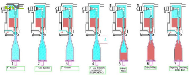
Two Triggers Set CIP Frequency on a Filling Line, and They Ask Different Questions
Summary: How Coverage, Shared Time and Frequency Fit Together
CIP cleaning on a filler ties coverage, shared time and frequency together into one specification. Incomplete path coverage fails silently, because a clean-in-place sub-step that never ran leaves no fault code and produces a hygiene result instead, and escalating the recipe aims at a variable that was never the problem. A stationary rotor turns the cleaning duration into an occupancy window, so a 30-to-60-minute format changeover and the clean-out-of-place work on stripped parts run inside a cycle that was already going to happen. Frequency is set by two independent triggers — a microbiological interval fixed by the product family, and a carry-over changeover fixed per product pair by a matrix that grows with SKU count. Coverage, occupancy and frequency are the three things a specification has to pin down.
Specifying the Filler Side of a CIP Circuit at Quotation Stage
Specifying the filler side of a CIP circuit at quotation stage means describing what the machine switches, wets and drains during a cycle — not which skid feeds it. From a procurement point of view that separation matters, because the skid, the chemical dosing unit and the chemicals themselves are counterparty equipment with their own suppliers and their own type designations. Laminar’s summary of that equipment fits in one line: a Type I skid makes fresh solution every cycle and sends it to drain, a Type II skid stores and re-doses it across cycles, and multi-loop stations share central tanks so several items clean at once. That line is where the skid conversation ends for a filling machine buyer.
The filler-side specification is a different list. The eight items below are the ones this article has established as decidable before a machine is ordered.
- Head count and commanded valves per head— the liquid valve and both gas-path control valves, stated per element and multiplied out, so the sub-step count has a denominator.
- Rinse cap supply and storage— one per filling element, with a defined home on the machine, since a cap that is hard to find is a cap that gets skipped.
- Rotor-stationary CIP capability— whether the control system can sequence the valves with the rotor at rest, which decides whether the window in the previous section exists at all.
- The sub-step list itself— a written enumeration of which paths each cleaning phase addresses, supplied as documentation rather than reconstructed from the programme later.
- Wetted-path construction— AISI 316L wetted parts, tri-clamp connections and a surface finish of Ra 0.8 µm (0.0008 mm / 31.5 µin) or better, which is the specification this site applies across its filling articles.
- Drainable geometry— the machine empties by gravity with no trapped pockets, because a pocket that holds rinse water dilutes the next stage and holds product between cycles.
- Cycle endpoint method— whether the cycle ends on a timer or on a measurement, since inline instruments can monitor the returning solution and detect residue rather than assuming a fixed time is sufficient.
- The COP parts list— which components come off for external cleaning, which is also the list that determines how much parallel work the cleaning window can absorb.
Validation belongs with that list rather than after it. The methods this site applies to hygienic filling equipment are visual inspection, total organic carbon measurement, ATP swabbing and microbiological testing, with ISO 22716 governing cosmetic production specifically. Each of those confirms a surface is clean; none of them confirms a surface was addressed. Procurement teams compare CIP skids and engineers who commission fillers compare sub-step lists — the two conversations use the same three letters and buy different things.
Where CIP Sits in a Malaysian Filling and End-of-Line Installation
CIP on a Malaysian filling installation sits at the upstream end of a line whose downstream half stops at the same moment. Food and beverage production and edible oils and oleochemicals are two of the industries DNC’s engineering work concentrates on, and both run wet product through a filler into containers that then move through the rest of the line. In terms of plant layout the filler and the capper form one machine block, and the conveyor that feeds them and the conveyor that takes containers away are idle for the whole cleaning cycle.
That idle period is the practical argument for treating the cleaning window as shared time rather than as a gap. The equipment downstream of a filler does not need cleaning in place, and it does need attention: belt tracking on the conveyors, format parts on the capper, and calibration on the weighing equipment that verifies what the filler produced. A batching and dosing weighing system upstream and a checkweigher downstream both come to rest during a filler CIP, which makes a cleaning stop the natural slot for verification work that otherwise demands a stop of its own.
Malaysian manufacturers running Industry 4.0 upgrades under NIMP 2030 tend to reach the control layer before they reach the hygiene layer, and the two meet at exactly this point. A clean-in-place programme with an enumerated sub-step list is a programme a control platform can log, timestamp and audit; a programme without one produces a completion flag and nothing behind it. Specification work of this kind belongs at the quotation stage of a filling line, and DNC’s engineers handle it as part of the commissioning scope for filling and end-of-line installations. If your production line is being specified or retrofitted this year, talk to our engineers about the sub-step list before the machine is built rather than after the first validation failure.
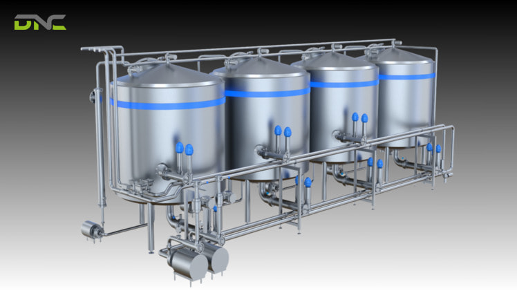
Where CIP Sits in a Malaysian Filling and End-of-Line Installation
Frequently Asked Questions About CIP Cleaning in Filling Lines
CIP cleaning in filling lines raises five recurring questions that the published material leaves open, and each is answered below.
What does CIP actually clean on a filling machine?
Clean-in-place cleaning on a filling machine reaches the interior of every filling element — the liquid path from the annular bowl through the liquid valve to the outlet, and the gas path through the return gas tube to the span gas space and the return gas collecting duct. Both circuits carry product contact, and both are reached only when their valves are commanded open. The bowl, the manifolds and the connecting pipework are cleaned in the same closed circulation.
Does the filling machine keep running during CIP?
The filling machine does not produce during CIP, and whether its rotor turns depends on the actuation design. Mechanically actuated fillers historically ran the cleaning cycle with the rotor turning at reduced speed, because cams and shift linkages tie every valve command to rotor angle. Electronically controlled valves allow the same sequence to run with the rotor at rest. One source on this topic claims cleaning happens while machines are in operation; that claim contradicts the closed-circuit definition of CIP and is not supported by any other published description.
What is a rinse cap and why does every head need one?
A rinse cap is a fitting seated under a filling element to seal its outlet so that cleaning solution returns to the circuit instead of discharging into open air. It appears in the source literature under three names — rinse container, rinse sleeve and CIP cap — and it is stated as a precondition for the cycle rather than as an accessory. Every head needs one because an uncapped element has no return path, so its circuit is open and its interior surfaces are not being circulated.
How long does CIP take on a filling line?
CIP duration on a filling line depends on the step count and the industry, and published figures run from 30 minutes to well beyond two hours. Standard three-step and five-step cycles are documented at 30 minutes to 2 hours, seven-step cycles in dairy and pharmaceutical plants at 60-90 minutes, and extended cycles in flavour and fragrance production at 5-7 hours. Filler cleaning specifically is described in the patent literature as requiring “a relatively long time … sometimes up to more than two hours” for one documented machine.
What does CIP not clean on a filling line?
Clean-in-place cleaning does not reach the components that have to come off the machine, and those are handled by clean-out-of-place instead. Fittings, joints, gaskets and seals are the standard COP items, along with spray devices whose nozzles clog and create shadow zones if they are not cleared periodically. On a filler the rinse caps themselves join that list, together with the format change parts that come off during a container-size conversion.
- 14 views
- 0 Comment
Recent Comments