


Strain Gauge Working Principle: Deformation Into Signal
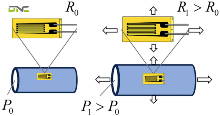
The strain gauge working principle is a chain of conversions, not a single effect. A force deforms a surface. The deformation transfers through an adhesive into a bonded foil grid. The grid’s geometry changes, which changes its electrical resistance. A Wheatstone bridge turns that resistance change into a voltage difference, and an amplifier turns the voltage into a number a controller can act on. Each link has its own physics and its own failure mode. Understanding the strain gauge working principle as a sequence – rather than as the single sentence “resistance changes with strain” – is what separates a gauge that reads correctly on a Malaysian production line from one that drifts within a month. This guide walks the chain link by link.
————————————————————
A Strain Gauge Converts Deformation Into a Resistance Change
A strain gauge converts the deformation of a surface into a proportional change in its own electrical resistance. It is a passive transducer: it generates no signal on its own and must be excited by an external voltage before anything can be read from it. The device is physically simple – a thin metallic foil pattern supported on an insulating flexible backing, bonded to the object under stress with an adhesive.
Two quantities get confused at this point, and the confusion propagates into every later calculation. Stress is the internal resisting capacity of an object under an applied force, expressed as σ = F/A in N/m². Strain is the amount of deformation the object actually experiences, expressed as:
ε = ΔL / L
where ΔL is the change in length and L the original length. Strain is dimensionless – numerator and denominator carry the same unit, so they cancel.
The distinction matters because a strain gauge measures strain, never stress. Stress is inferred afterwards from the material’s known elastic properties. A gauge bonded to aluminium and a gauge bonded to steel reading identical strain are reporting very different stresses, and any weighing or force system that skips that conversion step reports the wrong number with full confidence.
Resistance Changes Because Geometry Changes
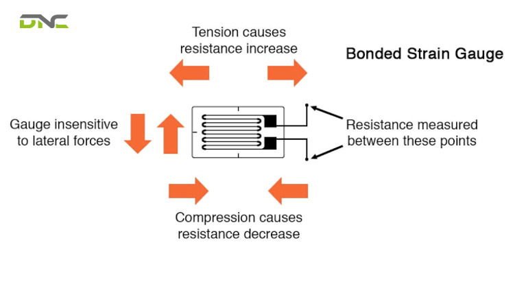
A strain gauge’s resistance changes because stretching a conductor makes it longer and thinner, and both changes push resistance in the same direction. The resistance of any conducting element depends on its resistivity, its length and its cross-sectional area. Resistivity is a property of the alloy and stays fixed; length and area are what deformation moves. Stretch a conductor within its elastic limit and it does not break – it becomes narrower and longer. Compress it and it becomes shorter and broader.
Under load, the two geometric changes are complementary:
- Under tension– length increases, cross-section shrinks. Longer path and narrower path both raise resistance. The two effects reinforce.
- Under compression– length decreases, cross-section grows. Shorter path and wider path both lower resistance. Again they reinforce.
This reinforcement is the reason the effect is usable at all. If the two geometric changes opposed each other, the net resistance change would be a difference between two similar quantities, and the residual signal would be far smaller than it already is.
The bond carries all of this. The gauge does not sense the object – it senses itself, and it only follows the object as faithfully as the adhesive layer and backing allow it to. Every strain reading is, strictly, a reading of what happened to the foil.
The Gauge Factor Sets How Much Signal a Given Strain Produces
The gauge factor states how much fractional resistance change a strain gauge produces per unit of strain. It is the sensitivity coefficient of the device:
GF = ΔR / (R<sub>G</sub> × ε)
where ΔR is the resistance change caused by strain and R<sub>G</sub> is the resistance of the undeformed gauge. Rearranged for practical use:
ΔR / R = GF × ε
For common metallic foil gauges the gauge factor sits a little over 2. Where the gauge behaves as a simple elastic conductor, the factor relates to Poisson’s ratio µ through K = 1 + 2µ, which is why the value clusters where it does rather than being freely selectable by design.
How small is the change actually? Take the published worked case: a gauge with GF = 2 experiencing a strain of 0.001. Then ΔR/R = 0.002. On a 350 Ω (0.35 kΩ) gauge that is a shift of 0.7 Ω (700 mΩ) – and 0.001 is already a substantial strain for structural steel. Routine industrial measurements run one to two orders of magnitude below that.
That single arithmetic result explains the entire electrical design that follows. A fractional change of 0.002 or less cannot be read by putting an ohmmeter across the gauge, because the lead wires, the connector contacts and a few degrees of temperature drift all move the reading by comparable amounts. Everything downstream – the bridge circuit, the regulated excitation supply, the shielded cable, the instrumentation amplifier – exists to recover a signal that small from noise of the same order.
The Gauge Factor Sets How Much Signal a Given Strain Produces
The Wheatstone Bridge Makes the Change Readable
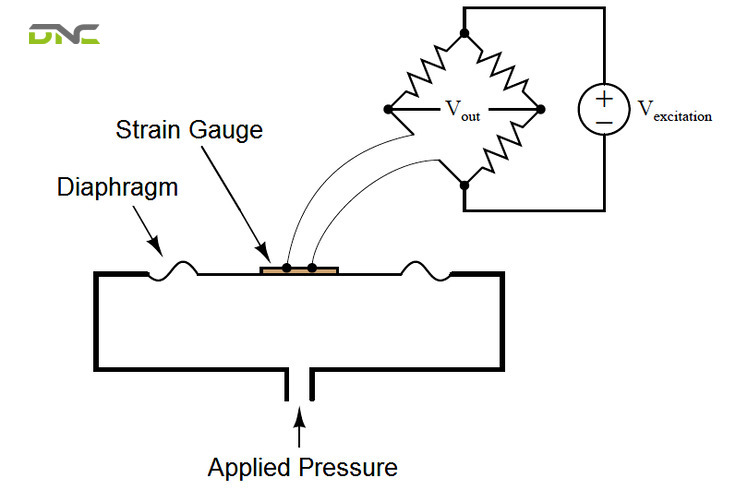
The Wheatstone bridge in a strain gauge circuit turns a resistance change too small to measure directly into a voltage difference an instrument reads reliably. It is a network of four resistive arms arranged in a diamond, with an excitation voltage V<sub>ex</sub> applied across one diagonal and the output taken across the other. Electrically it behaves as two parallel voltage dividers compared against each other.
The bridge is balanced – output voltage zero – when the arm ratios match:
R1 / R2 = R4 / R3
Replace one arm with a strain gauge and the balance condition becomes a measurement. Any change in that arm’s resistance unbalances the divider pair and produces an output voltage that is a function of strain. Measuring a difference from zero, rather than an absolute resistance, is what makes a 0.7 Ω shift recoverable.
The bridge output relates to strain through the gauge factor and the excitation:
SV = EV × [(GF × ε) / 4]
where EV is the bridge excitation voltage.
What happens if only one gauge is active? A quarter bridge – one gauge, three fixed resistors – works, but it leaves temperature uncompensated and produces the smallest output of the available configurations. A full bridge typically stresses two gauges while two remain unstressed, which improves sensitivity and temperature stability at the same time, because thermal drift common to all four arms cancels in the ratio.
| Configuration | Active gauges | Output | Temperature behaviour |
| Quarter bridge | 1 | Lowest | Uncompensated – needs a separate correction |
| Half bridge | 2 | Intermediate | Partial common-mode cancellation |
| Full bridge | 4 (two stressed, two unstressed) | Highest | Best cancellation of common thermal drift |
The output arriving from a bridge is a millivolt-level electrical signal. Because it is electrical rather than mechanical, it survives long cable runs and reaches a remote digital readout – which is precisely why strain gauge sensing became the industrial default rather than a laboratory technique. In a plant, that millivolt signal is amplified, digitised and delivered to a controller, where it becomes a weight value, a reject decision on a checkweigher, or a torque limit on a drive. Integrating that half of the chain – amplifier, controller, and the Smart Manufacturing & Industry 4.0 Solutions layer above it – is where a measurement stops being physics and starts being a production decision.
Summary So Far
The strain gauge summary so far runs four conversions deep. Force produced deformation. Deformation changed the foil’s geometry. Geometry changed resistance by a fraction of roughly 0.002 at most. The bridge converted that fraction into millivolts. Everything remaining in this guide is either a variation on how the first conversion is performed, or an account of how one of the four links breaks.
What happens if only one gauge is active?
The Zig-Zag Grid Raises Resistance, Not Sensitivity
The zig-zag grid pattern raises the gauge’s absolute resistance without raising its fractional response to strain. This is the point where published explanations openly disagree, and the disagreement is worth resolving because it changes what an engineer expects from gauge geometry.
One position, common among component suppliers, is that the resistance wires are folded into a zig-zag of parallel lines to increase their effective length within a small footprint. The other position, argued by geotechnical instrument manufacturers, is that the pattern does not increase sensitivity, since the percentage change in resistance for a given strain is the same for the whole strip as for any single trace – and that the real reasons are thermal, because a single long trace is liable to overheating, which itself changes resistance and corrupts the measurement.
Both statements about the strain gauge grid are correct, and they answer different questions.
Folding the conductor raises absolute resistance R. A 350 Ω gauge in a 5 mm (0.20 in / 0.005 m) footprint is only possible because the conductor is folded. But gauge factor governs the fractional change ΔR/R, and that fraction is a property of the material and the strain, not of how the conductor is routed. Doubling the folded length doubles both R and ΔR, leaving the ratio untouched.
So the pattern buys two things – a useful resistance value in a small sensing area, and distributed heat dissipation – and buys no extra sensitivity at all. An engineer who selects a longer-grid gauge expecting a stronger fractional signal has misread the geometry. What a longer grid actually changes is the area over which strain gets averaged, which is a spatial resolution decision, not a sensitivity one.
Strain Gauge Types Split Across Three Independent Axes
Strain gauge types divide along three axes that most references present as one list. A gauge carries a designation on each axis simultaneously – a foil gauge is also an electrical gauge and also a bonded gauge – which is why flat lists that place “bonded” next to “semiconductor” as alternatives create confusion during specification.
Axis 1 – Working principle: how deformation is detected
| Principle | Detection mechanism |
| Electrical (resistive) | Resistance change from geometry change – the industrial default |
| Mechanical | Direct physical readout, e.g. a pointer moving over a ruled scale as a crack opens |
| Optical | Light-based detection |
| Acoustical | Sound-based detection |
| Pneumatic | Air-pressure-based detection |
| Piezoelectric | Voltage generated by the material under strain |
| Vibrating wire | Frequency shift of a tensioned wire |
Axis 2 – Mounting: how the gauge is attached
| Mounting | Description |
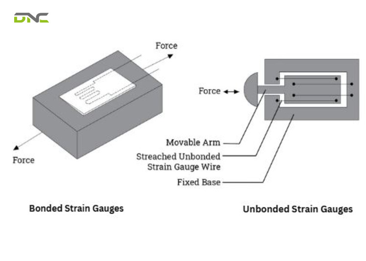
| Bonded | Sensing element cemented directly to the strained surface – metallic wire, etched foil, deposited film, or semiconductor bar |
| Unbonded | Wire stretched between two points in an insulating medium such as air; one end fixed, the other attached to a movable element |
Axis 2 – Mounting: how the gauge is attached
Axis 3 – Construction: what the sensing element is made of
| Construction | Characteristics |
| Foil | Metal foil photo-etched into a grid on a thin resin insulator; the most common form |
| Thin film | Resistive layer deposited directly onto the component by vacuum or sputtering, so the sensing layer becomes part of the part itself – better stability at high temperature and in harsh environments |
| Semiconductor | Silicon or germanium piezoresistors; preferred for very small strain, and they respond to stress rather than strain |
| Capacitive | Two conductive plates separated by an air gap or dielectric; strain changes plate separation or overlap, altering capacitance |
| Photoelectric | Light beam, two fine gratings and a photocell detector generating a current proportional to strain |
Two of these break the resistance model entirely and deserve separate treatment. Vibrating wire gauges anchor one end of a tensioned magnetic wire and displace the other in proportion to strain; changing tension changes the wire’s resonant frequency, and strain is proportional to the square of that frequency. Nothing about that measurement is resistive. Capacitive gauges likewise report a capacitance, not a resistance, and reach very small deformations that foil struggles with.
The historical sequence explains why foil dominates. Lord Kelvin reported the relationship between strain and the resistance of wire conductors in 1856. In the early 1930s Charles Kearns used bonded resistance gauges to measure vibratory strain in high-performance propeller blades. Arthur Ruge established in 1937–38 that small-diameter wires of resistance alloy could be bonded to a structure to measure surface strain, and the bonded resistance strain gauge was invented in 1938 by Edward E. Simmons and Arthur C. Ruge. Foil etching arrived in 1952, when Saunders-Roe adapted emerging printed-circuit methods to etch the gauge pattern from thin foil – the manufacturing step that made the modern gauge economical to produce and repeatable. When a strain gauge is discussed today without qualification, it is a bonded foil resistive gauge, and the Load Cell Types Explained guide covers how that default gets packaged into finished force sensors.
Every Measurement Error Breaks One Link in the Chain
Each documented strain gauge error corresponds to one broken link in the conversion chain. Error lists are usually presented as an unordered set of warnings; mapped back onto the chain, they become diagnosable – a symptom points to a link, and the link points to a fix.
| Error source | Link it breaks | Effect on the reading | Documented remedy |
| Improper bonding | Deformation → foil | Foil under-follows the surface; unstable signal | Surface preparation matched to material and to irregular geometry |
| Temperature change | Foil → resistance | Gauge resistance shifts with no strain applied | Temperature-compensated gauges, a thermistor correction, a dummy gauge in the bridge, or a full-bridge configuration |
| Lead wire resistance | Resistance → bridge | Wire resistance adds into the measured arm | Four-wire connection, where voltage is detected directly across the gauge element so lead wires do not affect the value |
| Electrical noise / EMI | Bridge → amplifier | Millivolt signal corrupted before amplification | Shielding and signal conditioning |
| Humidity and moisture | Foil and bond | Progressive drift, then instability | Protective encapsulation of the gauge and bond line |
| Mechanical misalignment | Deformation → foil | Gauge reads a component of strain, not the intended axis | Alignment during installation |
| Vibration | Deformation → foil | Superimposed dynamic content on a static reading | Signal conditioning matched to the measurement bandwidth |
| Gauge length vs strain field | Deformation → foil | Non-uniform strain fields cannot be read at a point; error scales with gauge length and width | Gauge length chosen against the strain gradient |
Three of these strain gauge error sources deserve elaboration.
Temperature is the dominant error source, and it is dominant because it attacks the same variable the measurement uses. A temperature shift changes the gauge’s resistance directly, with no force applied anywhere. The remedies all work by the same logic: put an identical, unstrained gauge in the same thermal environment and let the bridge subtract the common component.
Gauge length is a resolution constraint, not an accuracy specification. Strain cannot be measured at a point by any type of gauge, so every reading is an average over the active length. Short gauges resolve localised strain concentrations; long gauges average over a wider area and smooth them away. Choosing one is a decision about what you intend to see.
Why can a gauge read correctly in a lab and drift on a line? Because the lab exercises the first two links and the plant exercises all six. Bench calibration – applying a known load, measuring the output signal, comparing it against theoretical strain – validates the conversion when the bond is fresh, the temperature is stable and cable runs are short. A washdown bay with a 15 °C (27 °F / 288 K) daily swing, a variable-speed drive nearby and 30 metres (98 ft) of cable to the panel stresses links the bench never touched. A bonded gauge that has been removed cannot simply be re-bonded either; removal generally damages the grid or backing, which rules out reuse as a recovery path. Mechanical gauges are the exception – they are reusable, which is much of their remaining appeal.
A Strain Gauge Is a Component; a Load Cell Is the Assembly
A strain gauge is the sensing element; a load cell is the finished assembly that carries strain gauges on a machined spring element. The relationship is containment, not comparison – load cells contain strain gauges, and the gauge is the reason a load cell works at all.
The intermediate piece is the part that gives the gauge something to read. A load cell body is machined so that a specific region deforms predictably under load; that region is the strain generator, or spring element. Gauges are bonded to it and wired into a bridge. Applied force strains the element, the element strains the gauges, and the bridge outputs a voltage proportional to load.
| Parameter | Strain gauge | Load cell |
| Definition | Sensing element that measures strain | Complete force measurement device |
| Main function | Detects surface deformation | Measures applied force or weight |
| Structure | Thin metallic grid on a backing | Metal body with embedded strain gauges |
| Output | Resistance change | Voltage signal via the bridge circuit |
| Measurement | Strain | Force or weight |
| Installation | Bonded directly to a surface | Installed as a standalone sensor |
| Wiring | Needs bridge configuration | Built-in wiring and circuitry |
| Calibration | Requires external calibration | Factory calibrated |
| Role | Basic sensing element | Integrated measurement system |
One boundary is worth stating explicitly because it decides whether a load cell is the right instrument at all. A strain-gauge load cell measures the force applied at one point – it is a one-dimensional instrument. It cannot report how pressure is distributed across a surface. A packaging line that needs to know whether a sealing bar is applying even pressure across its whole width is asking a two-dimensional question, and no single load cell answers it.
Beyond weighing, the same principle carries into torque, pressure and structural monitoring. Gauges bonded to a diaphragm turn a pressure transducer into a strain measurement. Gauges on a rotating shaft measure the torque a motor, turbine or engine delivers to a fan, generator, wheel or propeller, where early detection of overload protects the reliability of the drivetrain. In aerospace, gauges on aircraft structural members measure wing deflection; gauges on rails measure axial tension and compression without loading the rail; gauges in automotive chassis and suspension testing map stress distribution under driving conditions. In a factory, the same physics appears as a checkweigher rejecting an underweight pack on a moving Conveyor System Solutions for Factory Automation line, a filling machine closing its valve on target weight, and a palletiser confirming pack mass before it stacks.
For Malaysian manufacturers, that last point is where the principle meets commercial reality. Weight accuracy on a filling or checkweighing line is simultaneously a giveaway cost, a regulatory exposure and a data source feeding the Industry 4.0 reporting that NIMP 2030 incentives are structured around. Factories that defer instrumenting these measurements do not merely lose accuracy – they lose the production data that later automation investment is justified with, and they enter the incentive window with a higher cost basis than competitors who instrumented earlier.
Strain Gauge Working Principle – Frequently Asked Questions
Seven questions recur whenever the strain gauge working principle is explained to an engineering team, and each one turns on a distinction the single-sentence definition leaves implicit.
What Is the Working Principle of a Strain Gauge?
A strain gauge works on electrical conductance and its dependence on the conductor’s geometry. When the surface it is bonded to deforms, the gauge’s foil grid stretches or compresses, changing its length and cross-sectional area, and therefore its electrical resistance. That resistance change is proportional to the applied strain and is read through a Wheatstone bridge.
What Is the Gauge Factor of a Strain Gauge?
The gauge factor is the sensitivity coefficient, defined as GF = ΔR / (R<sub>G</sub> × ε). It states the fractional resistance change produced per unit strain. For common metallic foil gauges it is a little over 2, a value that follows from the material’s Poisson’s ratio through K = 1 + 2µ.
Why Is a Wheatstone Bridge Used With a Strain Gauge?
A Wheatstone bridge is used with a strain gauge because the resistance change produced by strain is too small to measure directly. At GF = 2 and a strain of 0.001, the fractional change is only 0.002. A bridge measures the departure from a balanced null rather than an absolute resistance, which recovers a change of that size. A four-wire connection is the main alternative, and it works because the voltage is detected directly across the gauge element so lead wire resistance does not affect the value.
What Is the Difference Between Stress and Strain?
The difference between stress and strain is which quantity each one describes. Stress is the internal resisting capacity of an object under load, σ = F/A, expressed in N/m² (1 N/m² = 1 Pa). Strain is the deformation the object experiences, ε = ΔL/L, and is dimensionless. A strain gauge measures strain; stress is calculated afterwards from the material’s elastic properties.
What Is the Difference Between Stress and Strain?
What Is the Difference Between a Strain Gauge and a Load Cell?
A strain gauge is a sensing element that detects surface deformation and outputs a resistance change. A load cell is a complete force measurement device: a machined metal body with strain gauges bonded to its spring element, wired into a bridge, factory calibrated, and delivering an amplified voltage output. Load cells contain strain gauges.
Can a Strain Gauge Be Reused After Removal?
A bonded strain gauge cannot. Removing it usually damages the grid or the backing, which makes accurate reuse impossible. Mechanical strain gauges are the exception and are reusable, which alongside low cost is their main advantage.
Can Strain Gauges Measure Vibration and Dynamic Loads?
Strain gauges measure vibration and dynamic loads. With appropriate signal conditioning and high-speed data acquisition, they resolve rapidly changing strain as well as static strain. Gauges built specifically for high-frequency response are used for dynamic stress monitoring where load changes rapidly.
If your line depends on weight or force accuracy – filling, checkweighing, palletising, or force-controlled assembly – the gauge is only the first of six links, and the ones downstream are where readings are usually lost. DNC’s 35 engineers specify the sensor, the bridge configuration, the signal conditioning and the controller interface as one measurement chain, on more than 1,000 completed projects since 2005. Plants that want that chain reviewed before accuracy becomes a giveaway cost can Get a Free Consultation with the engineering team.
- 29 views
- 0 Comment
Recent Comments