


How a Liquid Filling Machine Works | DNC Automation Malaysia
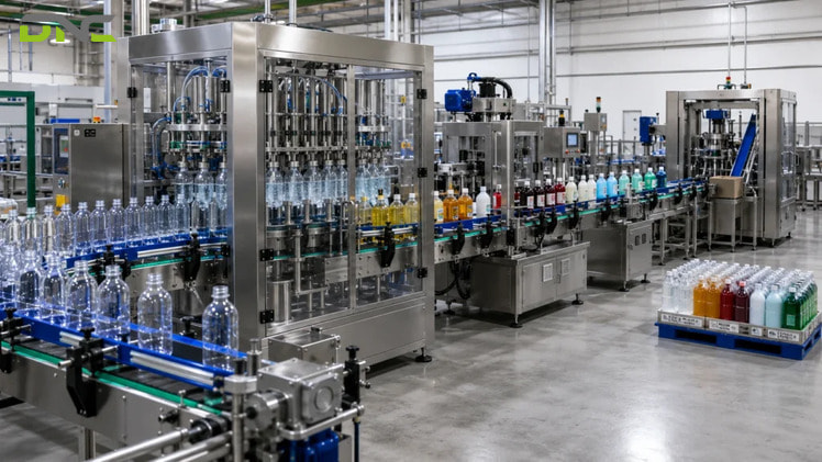
A liquid filling machine performs three separable functions: it handles the container, meters the product, and verifies the fill. Handling is the invariant — a conveyor delivers the container, a photo-eye sensor finds it, a stop holds it under the nozzle. Metering is where machines diverge, because every liquid filling machine holds exactly one of four quantities constant during a dose — elapsed time, liquid level, displaced volume or delivered mass — and lets the other three drift. In a gravity filler, head pressure supplies the driving force while the clock does the metering; a piston displaces a set volume per stroke; net-weight filling measures mass directly and is the only family governed by an international recommendation, OIML R 61-1:2017. Which family belongs on a given liquid filling machine is settled by the product before any catalogue is opened, and the point where the fill gets verified follows from the same decision.
A Liquid Filling Machine Moves the Container, Meters the Product, and Confirms the Result
From a production-line point of view, a liquid filling machine performs three separable functions: container handling, product metering, and fill verification. The three are built by different disciplines and fail for different reasons, which is why treating a filler as one indivisible box makes most enquiries harder to quote.
Container handling covers presentation, indexing and discharge. Containers arrive from an unscrambling table, an automatic dispenser or an operator; the machine aligns each one under a filling head, holds it while the dose is released, then releases it to the next station. Universal Filling Machine Company sets out that outer frame as five steps — container infeed, indexing and positioning, filling cycle, nozzle retraction, container discharge. Strip the branding from any competing machine description and the same frame appears. Handling is the invariant.
Product metering is the variable. The metering head decides what a dose is before the valve opens, and the four ways of deciding are the subject of most of this article. A machine engineered for an automatic bottle filling line running one thin free-flowing product carries a different head from one running edible oil into containers of 20 litres (5.28 gallons / 20000 ml), even where the conveyor, the frame and the guarding are identical.
Fill verification closes the loop. Makwell describes using “sensors or some other kind of verification to ensure that each container has received the right quantity of product”, while Lodha Pharma names the interlock that runs on the input side — a No Bottle-No Fill mechanism that halts the cycle when no container is detected on the belt. Verification is the function most often dropped from a low-cost quotation, and the first one asked about after a customer complaint. The sequence those three functions run in is fixed, so it makes sense to walk it before opening the metering head.
Every Fill Cycle Runs the Same Six Steps Whatever the Metering Method Is
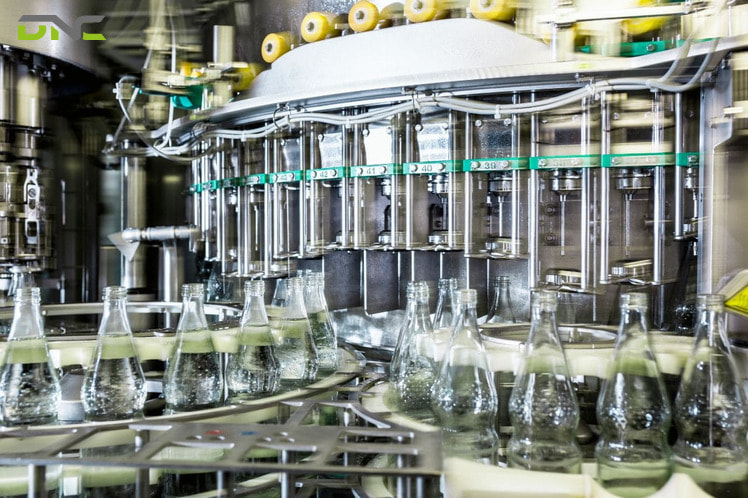
Viewed as a control sequence, a liquid filling machine repeats six steps per container, and only one of them changes with the metering method. Makwell names the six directly, and the sequence below matches the shorter descriptions published by Universal Filling and DFPACK.
The six steps of one fill cycle are listed below in the order the container experiences them.
- Container feeding— containers enter the machine manually, from an unscrambling table, or from an automatic dispenser, at a rate the filler can absorb.
- Positioning— conveyors, belts and guide rails align each container so the neck sits under the filling head, and a stop holds it there.
- Dispensing— the filling system releases product through a pump, a piston, a gravity valve or a weighed feed, continuously or in a discrete shot.
- Fill confirmation— a sensor, a weight reading or a level check verifies the container received the intended quantity.
- Sealing— the container is capped, lidded or heat-sealed, on the same frame or at the next station.
- Discharge— the filled container leaves for labelling, coding, case packing or palletizing.
Steps 1, 2, 5 and 6 are conveying problems with well-understood answers. Step 4 is a metrology problem. Step 3 is the one where two machines built for the same bottle behave nothing alike, and where the four controlled quantities come in.
Every Fill Cycle Runs the Same Six Steps Whatever the Metering Method Is
Four Quantities Can Be Controlled During a Fill, and Only One of Them Is Mass
In terms of what the machine actually regulates, every liquid filling method holds exactly one of four quantities constant — time, level, volume or mass — and lets the other three drift. Competing descriptions of this topic list six or seven method names in a flat sequence, which hides the fact that most of those names are implementations of the same underlying control. Classifying by controlled quantity is more useful at specification time, because the quantity a machine holds constant is the only promise it can keep.
The table below groups every liquid filling method described across the sources for this topic by the quantity its control system regulates.
| Controlled quantity | Methods that implement it | Held constant | Free to vary |
| Elapsed time | Gravity filling under a static head; time-based pump filling | Valve-open duration | Delivered volume, delivered mass |
| Liquid level | Overflow filling; vacuum filling | Fill height in the container | Delivered volume, delivered mass |
| Displaced volume | Piston filling; gear-pump filling with pulse timing; lobe and peristaltic pumps | Volume per stroke or per revolution | Delivered mass |
| Delivered mass | Net-weight and check-weight filling | Mass in the container | Fill height, delivered volume |
Read the right-hand column rather than the left. A piston filler that holds volume constant delivers a mass that moves with product density, and density moves with temperature — a real effect on an unconditioned Malaysian production floor where a morning batch and an afternoon batch of the same oil are not the same fluid. An overflow filler that holds level constant delivers a volume that tracks the moulding tolerance of each bottle. Neither machine is inaccurate; each is accurate about a different thing. The families are worth taking one at a time, starting with gravity and overflow filling — the two that hold a clock or a level rather than a quantity.
Gravity and Overflow Fillers Hold a Level and Let Volume Vary
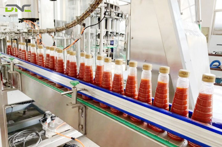
Considered as measurement systems, gravity and overflow fillers do not measure the product at all — one measures time, the other measures height, and both infer quantity from the result. Asset Packaging describes gravity filling as “a time-based feed from a tank located above the filling heads”, where “a valve under the filling head opens and allows the right amount of fluid to flow into the bottle before the valve closes after the allotted time.” Gravity supplies the driving force. The clock does the metering.
That distinction explains the conditions every source attaches to gravity filling. Delivered volume equals flow rate multiplied by valve-open time, so a constant time only yields a constant volume while flow rate holds — which requires a free-flowing liquid of consistent viscosity, no suspended particles that could obstruct the heads, and a supply head that does not fall as the tank empties. DFPACK lists the applications that satisfy those conditions: water, fruit juice, milk and wine, on high-speed lines at low cost.
Overflow filling swaps the clock for a geometric reference. The container fills until product overflows the nozzle and the excess returns to the supply tank, so every container carries the same fill height regardless of its internal volume. Asset Packaging states the trade honestly — overflow “focuses on filling bottles to the correct level, even if the process produces slight variations in volume” — and Makwell confirms it from the other direction, with containers filled “to a particular level independent of container size variances.”
That trade is correct for a product judged on a shelf. A row of clear bottles with a matched fill line reads as quality control, and a row with a visibly staggered line reads as a defect even where every bottle holds the declared volume. For a product sold by declared volume or net weight, the same trade pushes the compliance question downstream to a checkweigher instead of solving it at the filler. Products that must be right by quantity rather than by appearance need a head that displaces a measured amount.
Gravity and Overflow Fillers Hold a Level and Let Volume Vary
Piston and Pump Fillers Displace a Measured Volume
In volumetric terms, piston and pump fillers meter by moving a known volume of product per cycle rather than by timing a flow or watching a level. A piston filler draws product from the supply on its intake stroke and injects it into the container on the discharge stroke, through a valve system that switches the barrel between the two. Because the volume comes from the swept length of the barrel, the metering is indifferent to how readily the product flows — which is why all five machine builders surveyed for this topic put pistons on the thick end of the viscosity range, handling creams, pastes, gels, sauces and products carrying particulates such as soups and fruit preparations.
Universal Filling Machine Company publishes fill volumes from 5 ml (0.17 oz / 0.005 L) to over 5 litres (5000 ml / 1.32 gallons) at typically ±0.5% for its pneumatically and mechanically operated piston range. Read that figure as an entry point rather than as a specification. A filling accuracy claim becomes checkable only when it carries three parts — the measurand it applies to, the fill band it was declared over, and the minimum fill below which it lapses — and a bare percentage carries none of them. The same 0.5% means one thing on a 5 ml dose and something else entirely on a 5-litre dose.
Pump filling replaces the barrel with a rotating element and meters by counting it. Asset Packaging describes the two control options plainly: fill volume set “by counting the number of gear revolutions through a process known as pulse timing”, or by running the pump for a preset time, “although this tends to be less accurate than pulse timing.” Lobe pumps and peristaltic pumps sit in the same family, the latter squeezing a tube so that product touches nothing but the tube bore. A servo motor driving the pump extends the viscosity range further.
Pumps trade accuracy for speed against pistons, which is why Asset Packaging places them on large containers “where accuracy is less critical” — the reasoning behind most automatic drum filling installations, where a drum of 200 litres (52.8 gallons / 200000 ml) tolerates a deviation that a bottle of 250 ml (8.45 oz / 0.25 L) would not. Volume control still leaves one gap: it says nothing about the state the product is in when it arrives, and that is a nozzle problem rather than a metering one.
Diving Nozzles and Vacuum Solve Container Problems, Not Metering Problems
From a mechanism point of view, bottom-up nozzles and vacuum filling belong to a different axis than gravity, piston and pump — they govern how product enters the container, not how much of it is released. Competing articles list all five as peers, which produces specifications that name a method twice and a measurand never.
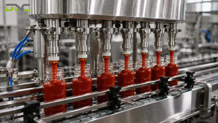
The clearest evidence sits inside a competitor description. Universal Filling Machine Company lists nozzle retraction as a step within its piston sequence: “in piston systems, the nozzles may dive into the container and retract (bottom-up filling) to prevent splashing or foaming.” The piston still sets the dose. What the diving nozzle changes is the distance product falls and the air it entrains on the way down. Makwell states the effect and its application together — the method “reduces the amount of air introduced and the amount of agitation during filling”, which suits products that are frothy or viscous.
Vacuum filling sits on the same axis for the opposite reason: it manipulates the container atmosphere. Suction draws liquid in until it reaches a set level, with the container rim sealing against the nozzle, and Universal Filling reports the result as clean and precise with minimal foaming — chosen for thin free-flowing liquids in rigid containers such as glass, including perfumes, toners and light oils. Counter-pressure filling is the carbonated-product variant of the same idea; Asset Packaging describes a diffuser distributing liquid around the container wall while pressurised CO₂ holds constant pressure in the bottle and the nozzle vents excess gas.
Two axes therefore need answering in any filling enquiry, not one: what meters the dose, and what the dose meets on the way in. A line running foaming detergent might well need a piston head for the metering and a diving nozzle for the entry, and neither choice substitutes for the other. Only one of the four metering families measures mass, the quantity a pack label usually declares, and it is the only one a metrology standard reaches.
Diving Nozzles and Vacuum Solve Container Problems, Not Metering Problems
Net-Weight Filling Is the Only Method With a Metrology Standard Behind It
From a legal-metrology standpoint, net-weight filling is the only liquid filling method that measures mass directly, and the only one governed by an international recommendation. Asset Packaging gives the mechanism in one sentence — check weight machines “include a platform that monitors the weight of the liquid as it fills the container”, which suits large containers. No source surveyed for this topic goes further, and none names a standard.
OIML R 61-1:2017 covers exactly this instrument. It defines an automatic gravimetric filling instrument as one that fills containers with a predetermined mass “from bulk (including liquid material)” — the parenthesis is what places liquid filling inside the standard — and it names the parts a compliant machine consists of: a load receptor, one or more feeding devices, and a control device made up of a feed control device, a fill setting device, a final feed cut-off device and an optional correction device. That correction device exists for a physical reason, and the standard states it directly: the final feed cut-off device may include a device that corrects for the residual material feed into the weighing module after cut-off. Product still in flight when the cut-off fires arrives in the container anyway, so the cut-off point sits ahead of the target by a margin the machine carries.
The standard also supplies the three parts a bare filling accuracy percentage leaves out.
- Accuracy class.Instruments are marked X(x), where x takes the form 1×10^k, 2×10^k or 5×10^k and is capped at 2. The maximum permissible deviation for class X(x) equals the base table value multiplied by x, so two physically identical machines marked X(0.2) and X(2) differ tenfold in what they promise.
- Fill band.Maximum permissible deviation runs as a staircase across nine bands rather than as one percentage — 7.2% of the fill up to 50 g (1.76 oz / 0.11 lb), a flat 3.6 g from 50 g to 100 g, 3.6% from 100 g to 200 g, 7.2 g from 200 g to 300 g, and on up to 0.8% above 15 kg (33.07 lb / 529 oz). In-service limits sit at exactly 1.25× the initial-verification limits in every band.
- Minimum fill.Below the rated Minfill, the accuracy claim does not apply at all. At a 1 g scale interval, that floor is 111 g (3.92 oz / 0.24 lb) for class X(0.2) and 11 g (0.39 oz / 0.024 lb) for class X(1) — a constraint no machine brochure states.
DNC specifies weighed filling against that regime rather than against a brochure figure, because it is the regime the instrument will actually be verified to. The mechanism is the same one behind a batching and dosing weighing system on a multi-ingredient line, and it rests on the same components: a load cell and indicator pair reporting mass to the control device that decides when the feed stops. Metering of any family, though, is only half a machine.
Summary: What Has Decided the Method So Far
Four things have now decided the liquid filling method. Gravity filling meters by the clock and needs a free-flowing product with a stable head, while overflow and vacuum filling meter by height and buy a matched fill line at the cost of volume variation. Piston and pump filling displace a measured volume and carry the widest viscosity range, with pistons more accurate and pumps faster. Net-weight filling measures mass and is the only family with a published class structure, fill-band staircase and minimum fill behind it, and diving nozzles and counter-pressure sit on a separate axis answering a separate question. What none of that establishes is what turns a metering head into a machine that can run unattended for a shift.
Net-Weight Filling Is the Only Method With a Metrology Standard Behind It
Sensors and Interlocks Turn a Metering Head Into a Machine
Under industrial control, a liquid filling machine is a sensor-driven state machine wrapped around a metering head. Four of the five machine builders surveyed state that sensors trigger the fill; none shows the loop. A published PLC training example does, and it is worth reading because it comes from a controls publisher rather than a machine seller.
That worked example runs three photo-eye sensors, a three-position selector switch setting off, manual or automatic, momentary switches for manual jogging, a conveyor belt motor, a drain valve and mode signal lamps. In automatic mode the sequence is: the start switch is pressed, the motor drives the conveyor until sensor 2 detects a container, the motor stops, the valve opens for a set interval — 7 seconds in that example — the valve closes, and the motor resumes, repeating until the stop switch is pressed. Sensors 1 and 3 count empty containers entering and filled containers leaving, and a reset switch clears both counts.
The counting pair deserves more attention than it usually gets. A machine that records how many containers entered and how many left produces a number that reconciles against a production record, which converts an operator claim into evidence. That capability is what separates a filler that participates in an Industry 4.0 data architecture under NIMP 2030 from one that simply runs. Lodha Pharma describes the adjacent interface layer on digital fillers — operator access to filler functions including indexing of the diving nozzle and system control — and Universal Filling lists touch-screen HMI, stored recipes and tool-free changeover as automatic-machine features.
Recipe storage matters more than it sounds on a line that changes product. Every parameter established so far — valve-open time, stroke length, target mass, cut-off point, nozzle depth — is a number that must be restored exactly at the next changeover, and restoring it from an operator notebook is where repeatability quietly disappears. How many of those parameters an operator touches at all depends on the automation level the machine is specified at, and on the frame layout it sits in.
Automation Level and Frame Layout Are Two Independent Specifications
In configuration terms, a liquid filling machine carries two independent specifications — automation level and frame layout — and a description that names only one of them is incomplete. Suppliers commonly present them as a single ladder, which leaves buyers comparing a semi-automatic inline machine against an automatic rotary one as though a single number separated them.
The grid below sets out the two axes a liquid filling machine is configured on, and what each one governs.
| Inline / linear frame | Rotary frame | |
| Manual | Bench-top filler, no power source required, operator places and triggers by hand | Not built at this level |
| Semi-automatic | Operator places the container, a button or foot pedal starts a preset dose | Uncommon |
| Fully automatic | Conveyor feeds containers in sequence past the heads; head count is the upgrade path | Containers travel on a carousel; rinsing and capping can share the frame |
The automation axis governs labour content. Asset Packaging describes manual machines as needing “no power source”, useful as bench-top units, while semi-automatic machines require “some human intervention, such moving containers in and out of the filling area”, and DFPACK adds that the semi-automatic trigger is typically a foot pedal or button. Fully automatic machines run infeed, dose and discharge without intervention.
The layout axis governs rate ceiling and flexibility. Asset Packaging reports inline machines as cost-effective, flexible and upgradeable because they fill containers passing along a conveyor in sequence, against rotary machines that are quicker and can incorporate bottle cleaning and capping technology, “but they tend to be more expensive and specialised for specific products and containers.” The engineering consequence is that flexibility and speed pull in opposite directions on this axis, so a plant running many SKUs and a plant running one at volume should reach different answers from identical throughput figures. Both axes, though, are things the machine adds once the metering method has already been chosen.
Automation Level and Frame Layout Are Two Independent Specifications
Summary: What the Machine Adds Once the Method Is Chosen
The machine adds two layers once the metering method is chosen. Sensors and interlocks convert a metering head into a state machine that will not fire into empty space and that counts containers in and out, which turns an operator claim into a reconcilable record. Automation level and frame layout sit on two independent axes, so labour content and rate ceiling are specified separately rather than as one ladder. Neither layer changes what the head measures. Both decide whether the measurement survives a full shift, a product changeover and an audit — which returns the question to the liquid that started it.
Specifying a Liquid Filling Machine Starts With the Liquid
From a specification point of view, the liquid determines the metering family before any machine is considered. Every source surveyed converges on the same short list of selection inputs — product viscosity, container type and size, desired fill rate, level of automation required, and available floor space — and every source puts viscosity first. Working the list in that order inverts the usual enquiry, which tends to open with a machine type and a bottles-per-hour figure.
Four liquid behaviours cover the field, and each one closes off part of the filling option set.
Free-flowing liquids keep every option open
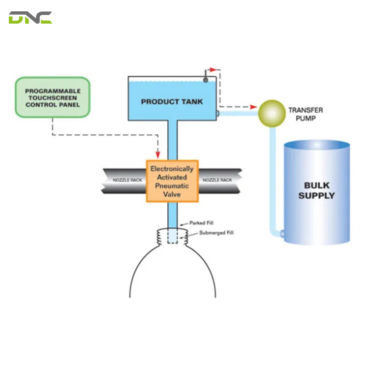
Free-flowing liquids of consistent viscosity — water, juice, milk, wine, light oils — accept gravity, overflow, vacuum, pump and piston heads. The choice falls to container appearance and declared quantity rather than to the product, so a clear retail bottle points to overflow and a drum points to a pump.
Free-flowing liquids keep every option open
Viscous products remove the passive methods
Viscous products remove the gravity and overflow fillers from the option set, because creams, pastes, gels, honey, syrups and heavy sauces will not flow usefully under a static head. Pistons handle them by displacement, and pumps handle them with a servo drive; a diving nozzle is usually added so the product is laid in rather than dropped.
Foaming products are a nozzle problem before they are a metering problem
Foaming products defeat accurate metering at the nozzle, because foam occupies the headspace the dose needs. Bottom-up filling addresses the cause by limiting the fall distance and the agitation, and counter-pressure filling addresses it for carbonated products by keeping the container under pressure while it fills.
Particulate-bearing products need a clear path
Particulate-bearing products need a filling path wide enough to clear the solids, because soups, fruit preparations and chunky sauces obstruct gravity heads and shear in tight pump clearances. Pistons handle them because the flow path is short and wide, which is why piston fillers dominate this behaviour class.
Malaysian production reality adds a fifth input that no supplier checklist names: what else the liquid does on the floor. Edible oils and oleochemicals change density across a working day in an unconditioned plant, latex compounds in glove manufacturing shear-thin under pumping, and water-treatment chemicals impose material compatibility on every wetted part. Those behaviours belong in the enquiry before a machine type does. Once the head is settled, the constraint moves outward to the stations the container passes through before and after the filler.
The Filler Is One Station in an End-of-Line Sequence
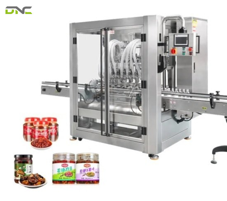
Across a full packaging line, the filler is one station whose rate sets the rate of the stations around it and is limited by them in turn. Asset Packaging sets out the surrounding sequence in detail: unscrambling tables or automatic dispensers presenting containers at regular intervals, wash or pre-sterilisation stages on hygiene-critical products, conveyors moving containers “from process to process with regular frequency”, then capping, then labelling, then shrink wrapping or cartoning, or an accumulation table for manual handling.
Each of those handovers is a rate and a tolerance, not just a connection. A filler that indexes four containers at a time hands off in bursts, so the conveyor system automation between it and the capper has to buffer rather than merely transport. A capper that stalls backs pressure up to the filling heads within seconds. Malaysian food and beverage, edible oil, glove and water-treatment plants all run this same chain with different products passing through it.
Verification usually sits downstream rather than at the head. A volumetric or level-based filler cannot report mass, so plants declaring net contents place a checkweigher after the capper to catch under-fills and over-fills before the pack is labelled — the compliance step that the overflow trade-off deferred earlier in this article. From there the containers move to case packing, carton sealing machine stations, and robotic palletizing at the end of the line.
DNC engineers, supplies and commissions those stations as one sequence rather than as separate purchases, which is where most of the difficult questions surface. The metering head is rarely the part of a filling line that a plant gets wrong; the rate matching between the filler and the two stations either side of it is.
The Filler Is One Station in an End-of-Line Sequence
Frequently Asked Questions About How a Liquid Filling Machine Works
The questions below come up most often during filling line enquiries.
Does a gravity filling machine measure volume?
A gravity filling machine measures time, not volume. The valve under the filling head opens for a set interval and closes, so delivered volume is the product of flow rate and that interval — accurate only while flow rate holds steady, which requires a free-flowing liquid and a stable supply head.
What is the difference between overflow filling and level filling?
Overflow filling is one way of achieving level filling. Both hold fill height constant across containers; overflow does it by filling until product spills into a return path back to the supply tank, and vacuum filling does it by drawing product to a set level with suction while the container rim seals against the nozzle.
Can one filling machine handle both thin and thick liquids?
A piston filler can cover the widest viscosity span of the four metering families, because it displaces a fixed volume rather than relying on the product to flow. Product changeover still requires the fill volume, nozzle type and often the nozzle depth to be reset, so span across viscosities is not the same as running both without adjustment.
How does a filling machine know a container is present?
Photo-eye sensors detect the container and trigger the dose, and the interlock built on them prevents the head from firing into empty space — a mechanism marketed as No Bottle-No Fill. In published control examples the same sensor family also counts containers entering and leaving, which gives a reconcilable production record.
What does an accuracy figure like ±0.5% actually mean?
An accuracy figure means something when it carries three parts: the measurand it applies to, the fill band over which it was declared, and the minimum fill below which it lapses. OIML R 61-1:2017 supplies all three for weighed filling through accuracy class X(x), a maximum permissible deviation staircase across nine fill bands, and a rated Minfill.
Is a checkweigher needed after a liquid filling machine?
A checkweigher is needed wherever the pack declares a quantity the filler does not measure. Volumetric and level-based fillers control volume or height rather than mass, so net-content compliance is verified downstream; a net-weight filler measures mass at the head and shifts that burden forward.
Which is better, an inline or a rotary filling machine?
Neither filling machine frame is better in general, because they answer different constraints. Inline frames cost less, adapt to more container shapes and accept additional heads as an upgrade path; rotary frames run faster and can carry rinsing and capping on the same frame, at higher cost and narrower product range.
Talk to Our Engineers About Your Filling Line
Your filling line reduces to three decisions in sequence, and our engineers work them in that order: which quantity the head holds constant, what the product needs on the way into the container, and what the stations either side of the filler demand of it. DNC Automation engineers, supplies and commissions filling machines alongside conveyors, checkweighers, carton sealing and robotic palletizing as one end-of-line sequence, backed by 35 engineers, a production floor of 25000 sqft (2323 m2) and ISO 9001:2015 certification across 20 years of Malaysian manufacturing work.
If your line runs edible oils, beverages, latex compounds or treatment chemicals, the metering family and the verification point are worth settling before a machine is quoted. Bring us the liquid, the container and the rate, and the specification follows from there — talk to our engineers before the machine is chosen.
- 13 views
- 0 Comment
Recent Comments