


6 Axis Robot Arm: Reach, Payload and Usable Envelope
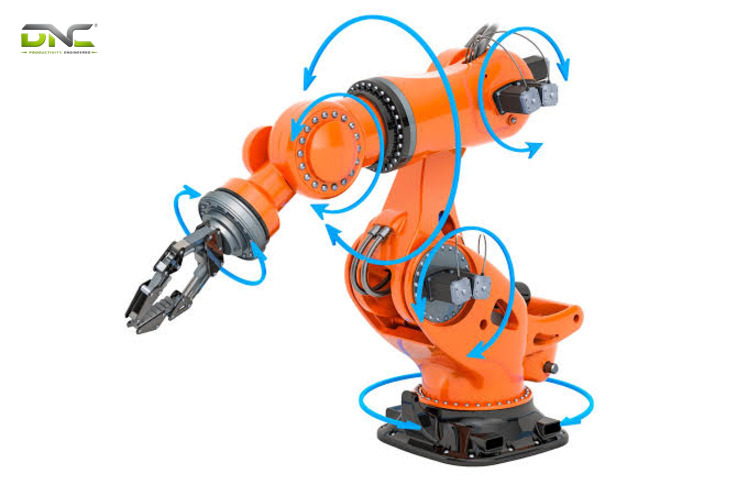
A 6 axis robot arm is an articulated robot with six rotary joints: three carry the wrist to a point and three turn the tool to the angle the task needs. Axis count tells you how the arm orients a gripper, torch or nozzle. It does not tell you what your production line can use. Five limits decide that: reach class, payload at the flange, singularity zones, repeatability against accuracy, and acceleration on short moves.
DNC Automation integrates Comau and Doosan robot arms into palletizing and end-of-line cells for Malaysian manufacturers. For plant engineers specifying a 6 axis robot arm, ISO 9283 definitions and published datasheet figures turn each limit into a number to check.
A 6 axis robot arm positions the wrist with three joints and orients the tool with three
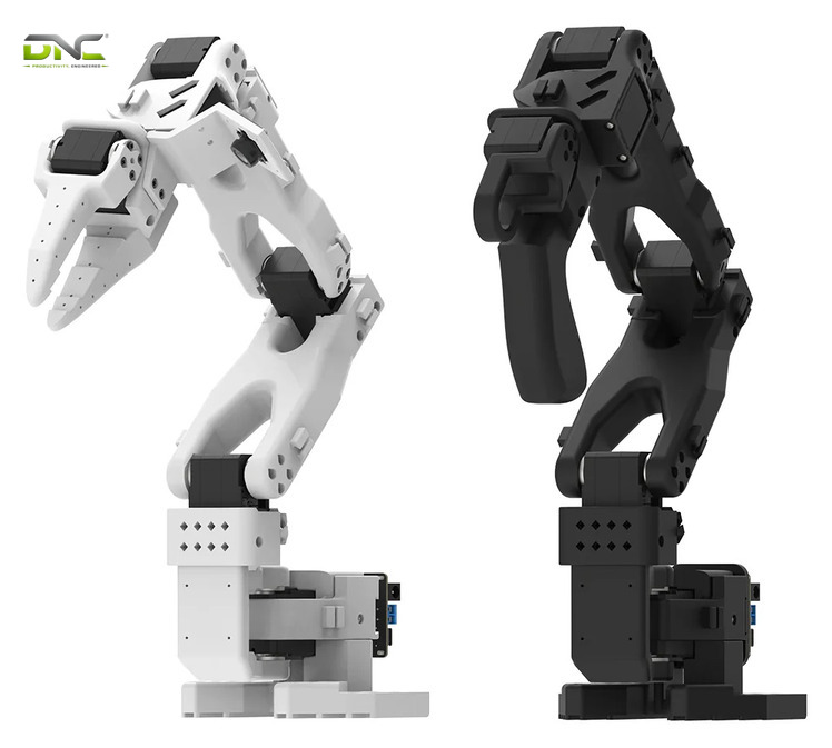
In kinematic terms, a 6 axis robot arm is a serial chain of six rotary joints, where joints J1 to J3 position the wrist and joints J4 to J6 orient the tool. Two axes reach any point in a plane and three axes reach any point in space. Three more wrist axes (yaw, pitch and roll) are needed to control the tool angle as well. The wrist does the orienting. Six is therefore the minimum for full freedom: movement along X, Y and Z plus rotation about each. A 5-axis arm cannot rotate the tool about one of those axes.
The terms “6-axis robot arm”, “articulated arm robot” and “articulated robot arm” describe one machine from three angles. “Articulated” names the rotary-joint design, and “6-axis” names the joint count. Articulated robots have six or more degrees of freedom, and some designs carry ten or more axes.
Six joints make up a 6 axis robot arm, and the table below names what each one sets.
| Joint | Name | Motion | What it sets |
| J1 | Base | Turns the whole arm about the vertical axis | Horizontal position |
| J2 | Shoulder | Tilts the arm up and down | Height |
| J3 | Elbow | Bends and extends the forearm | Reach distance |
| J4 | Wrist roll | Rotates the wrist | Tool rotation |
| J5 | Wrist pitch | Tilts the wrist | Tool tilt |
| J6 | Wrist yaw | Turns the tool flange | Tool heading |
Each joint holds a servo motor, a reduction gear that multiplies motor power, and an encoder that reports the shaft angle. A hollow wrist, offered on some models, carries air hoses and sensor cables through the arm. A 7-axis arm adds a redundant joint, so one tool position has several joint configurations, and that helps the arm avoid singularities. Joint count fixes how freely the tool turns. The size of the arm that carries it is set next, by reach and payload class.
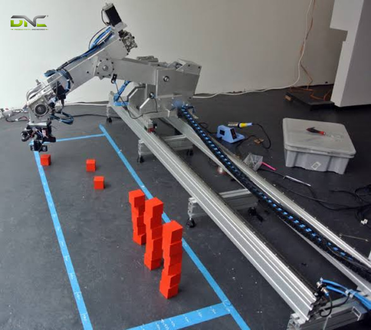
Reach and payload class set the arm size before any other figure
A 6 axis robot arm falls into a size group by reach and payload class before any other figure matters. One global OEM groups its articulated range into small robots with payloads up to 12 kg (26.5 lb), medium robots up to 60 kg (132 lb) and large robots up to 600 kg (1,323 lb). A robotics buyer’s guide puts high-end articulated arms above 1,000 kg (2,205 lb), against 10 to 20 kg (22 to 44 lb) for a large delta robot.
Published model pages show how the small 6-axis arm group looks on a datasheet. The figures below come from OEM pages crawled in November 2026, so treat them as examples, not as a current catalogue.
| Example series | Reach | Payload | Repeatability | Footprint or note |
| Bench-class 6-axis, OEM A | 653 or 855 mm (25.7 or 33.7 in) | Up to 5 kg (11.0 lb) | ±0.02 or ±0.03 mm (±0.0008 or ±0.0012 in) | Joint speed up to 600 °/s |
| Compact 6-axis, OEM B | 650 or 850 mm | 7 kg (15.4 lb) | ±0.020 or ±0.030 mm | 200 x 200 mm (7.9 x 7.9 in) base, 0.49 or 0.59 s cycle |
Reach is how far the arm extends from its base, and the working envelope is the region of space it can reach. A robot’s size group follows from the heaviest load and the farthest point in your cell. DNC supplies the arm as part of its industrial robotic solutions, so the size group is checked against the whole cell, not the arm alone. The payload figure in that table is the next limit, because the tool spends part of it before the product does.
Reach and payload class set the arm size before any other figure
Payload is a wrist allowance that the tool spends first
A 6 axis robot arm’s rated payload is the mass the wrist carries at the flange, and the end effector counts against it before the product does. One European robot-mechanics maker states that the payload choice must cover the workpiece, the attached grippers or welding torches, and the dynamic forces of rapid acceleration and deceleration. The rated figure is a ceiling for tool plus product, not for product alone.
Mass is only half of the wrist limit. One Japanese OEM publishes a maximum allowable moment of inertia of 0.295 kg·m² (7.0 lb·ft²) at joints J4 and J5 and 0.045 kg·m² (1.07 lb·ft²) at J6 for its 7 kg series, and describes that as 2.5 times the conventional figure. Inertia grows with the square of the distance between a mass and the joint axis. Inertia is the other half. A wide vacuum plate and a compact gripper of equal mass therefore load the wrist differently.
The arithmetic below is a DNC illustration, not a measured case. It shows how a carton and a tool move an arm between the size groups above.
| Carton | Tool | Load at the flange | 5 kg arm | 7 kg arm | Up to 12 kg class |
| 3 kg | 1.2 kg | 4.2 kg | Fits | Fits | Fits |
| 6 kg | 1.5 kg | 7.5 kg | Over | Over | Fits |
| 10 kg | 2.5 kg | 12.5 kg | Over | Over | Over |
The 10 kg carton looks small beside a 12 kg label. Add a 2.5 kg vacuum gripper and the load reaches 12.5 kg (27.6 lb), which moves the arm into the medium group. Dynamic load during acceleration raises the demand further. Even a load inside the wrist limit works only where the wrist can get to, and some reachable points sit in zones where the wrist loses control.
A reachable point is unusable inside a singularity
In terms of path planning, a 6 axis robot arm finds a reachable point inside a singularity unusable, because a singularity is a pose where two or more robot axes line up and the arm’s motion and velocities become unpredictable. The ANSI/RIA R15.06-1999 safety standard defines the term as the collinear alignment of two or more axes. A point inside such a pose is reachable on paper and unusable in production. Reach, then, is a map of where the tool can be, and the singularity zones mark where it cannot be controlled.
Two mitigations appear in the literature. Some manufacturers alter the path slightly to avoid the condition, or the travel slows so the wrist needs less speed to pass through. ANSI/RIA also requires manufacturers to make the user aware of a singularity that occurs during manual manipulation. A 7-axis arm avoids the problem by adding a joint. A 6-axis cell avoids it by design: the taught path is checked against the three zones below before teaching begins.
Wrist singularity and the wrist flip
A wrist singularity occurs when axes 4 and 6 line up, and axis 5 then tries to spin 180° in zero time to hold the tool angle. That sudden spin is called a wrist flip. It is most common in arms with a triple-roll wrist, where all three wrist axes pass through one common point. The result is dramatic, with adverse effects on the arm, the end effector and the process.
Holding the tool straight in line with the forearm brings axes 4 and 6 into line. The tool angle at each taught point decides the risk, not the arm brand.
Shoulder and plane singularities
Shoulder and plane singularities are two further poses of the same kind. A shoulder singularity occurs when the wrist center lies on a cylinder around axis 1, with a radius equal to the distance between axes 1 and 4, and joint 1 then spins very fast. A third type occurs when the wrist center lies in the same plane as axes 2 and 3. Some manufacturers also name an alignment singularity, where axes 1 and 6 coincide, and treat it as a sub-case of the shoulder type.
All three types share a root cause: axes line up and one joint must make up the difference. Where the arm can go safely is one question. How closely it lands there is the next.
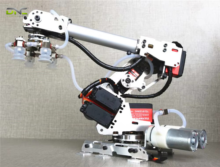
Repeatability and accuracy are different figures on the same datasheet
On a 6 axis robot arm datasheet, repeatability is how closely an arm returns to a taught position, and accuracy is how closely it reaches a commanded position. The two figures are not the same measure. A robot told to go to a given X-Y-Z coordinate may land within 1 mm (0.039 in) of it, which is its accuracy. If that point is taught and the robot returns to within 0.1 mm (0.004 in) every time, the repeatability is 0.1 mm. Calibration improves accuracy, and repeatability is usually the more important criterion.
ISO 9283 defines the test. The robot visits a taught position several times, each time after visiting four other positions, and repeatability is the standard deviation of the errors in all three dimensions. Both figures change across the working envelope and with speed and payload, so a single number describes one test condition only.
Datasheets use the words loosely. One supplier in Malaysia quotes “positioning accuracy” between ±0.02 mm and ±0.05 mm for its 6-axis arms, while two OEM series pages list “repeatability” between ±0.02 mm and ±0.07 mm. The ranges overlap and the quantities differ. The table below separates what each term decides in a cell.
| Datasheet term | What it measures | Matters most when |
| Repeatability | Return to a taught point | A palletizing pattern is taught once and run for months |
| Accuracy | Arrival at a computed point | A vision system or offline program supplies the coordinates |
| Both, at speed and load | Drift with payload and move length | The cell runs near its rated payload |
Repeatability and accuracy are different figures on the same datasheet
A robotics buyer’s guide adds that some tasks need micron-level precision, which most articulated arms cannot reach, and that cartesian robots outperform them there. Four limits now cover where the arm reaches, what it carries, where it loses control and how closely it lands.
Summary: Four limits separate reach from usable reach
For a 6 axis robot arm, four limits separate reach from usable reach: reach and size group fix the first figure, and the tool-loaded payload fixes the second. Singularity zones remove points from the usable envelope, and repeatability against accuracy decides how closely the remaining points are hit. A datasheet shows the first of these as a headline number and the others as footnotes or not at all. A 6 axis robot arm earns its place in a cell only when the load at the flange, the taught path and the placing tolerance all sit inside those four limits. The fifth limit is time.
Acceleration, not top speed, sets a 6 axis robot arm on short moves
A 6 axis robot arm reaches its rated top speed only on long, uncomplicated moves, because acceleration limits the speed it builds on short ones. On a short move or a path with frequent changes of direction, the arm never reaches its specified maximum. Published joint speeds range widely: one OEM lists up to 600 °/s depending on joint, and another lists 210 °/s for J1 to J3 and J5, 225 °/s for J4 and 450 °/s for J6. Joint J6, which turns the tool, is the fastest in that list.
A robotics buyer’s guide puts six-axis speeds in the hundreds of degrees per second and standard delta robots above 1,000 °/s. A cycle time such as 0.49 s on a compact OEM series page comes without the move length, so it is a comparison point, not a promise for your layout. The table below compares the arm types that a manufacturing robot arm decision usually weighs.
| Arm type | Strength | Limit |
| 6-axis articulated | Full tool orientation, payloads to 1,000+ kg | Speed in the hundreds of °/s; singularities |
| 5-axis articulated | Fewer joints, faster cycle times on repetitive picking and palletizing | No rotation about one axis |
| 7-axis | Avoids singularities, reaches around obstacles | Redundant seventh joint |
| Delta | Above 1,000 °/s on light picks | Large units carry 10 to 20 kg |
| SCARA | Trades motion range for cost, speed and accuracy | Limited tool angles |
| Cartesian | Extreme precision | Needs three added rotary axes to orient the tool |
For shared workspaces, the collaborative version of the articulated arm is built to work beside people, as the DNC guide to cobot vs industrial robot palletizers sets out. The arm type is one choice, and the application then decides which limit dominates it.
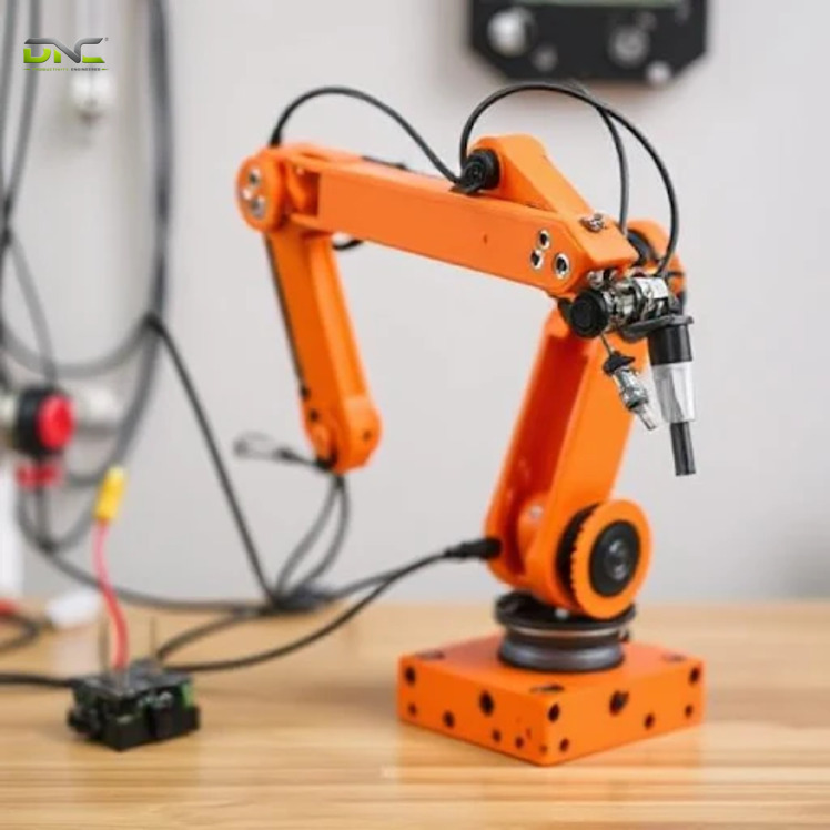
A 6 axis robot arm meets a different limit first in welding, assembly and material handling
A 6 axis robot arm meets a different limit first in welding, assembly and material handling, because each task stresses a different part of the arm. The applications below are the ones named most often across manufacturing robot arm guides: material handling (palletizing, pick and place, bin picking), welding, assembly and machine tending.
The table below maps each task to the limit that dominates it, using the industry notes from one robotics buyer’s guide.
| Task | Typical industry | Dominant limit |
| Welding | Automotive, metals | Wrist angles and singularity zones, since SCARA and delta robots cannot reach the required angles |
| Assembly | Electronics | Repeatability, with micron-level work beyond most articulated arms |
| Machine tending | Metals, automotive | Reach to the machine door and the cycle for loading and unloading |
| Palletizing and pick and place | Food and beverage, packaging | Payload at the flange and reach over the pallet |
| Pick and place in cleanrooms | Pharmaceuticals | Sealed joints and protective sleeves |
Automotive parts are often large and heavy, so high payloads and long reach are common requirements there. Palletizing and case handling put the carton first, which is where a packaging line’s own equipment decides the arm. The arm choice only holds once the arm sits in a cell, where the carton sets the specification.
A 6 axis robot arm meets a different limit first in welding, assembly and material handling
In an end-of-line cell the carton, not the arm, sets the specification
In an end-of-line cell, a 6 axis robot arm is specified by the carton arriving from the sealer: its mass sets the payload case, and its pattern sets the tool and the approach angles. The case closes at the carton sealing machine and is weighed at the checkweigher, so the heaviest carton the checkweigher accepts is the figure the arm must carry, not the label mass printed on the case. Tool mass is added to that number, and the sum goes against the rated payload. Label mass is not the figure.
DNC’s palletizing work starts from that figure. The heaviest accepted carton is the first number requested for a cell, ahead of the arm model. The place pattern then fixes the tool angle at each layer, which tells the programmer where J4 to J6 must turn and where a wrist flip is a risk. DNC integrates Comau and Doosan robots into robotic palletizing cells on exactly this basis.
Engineers tend to compare arms by reach and procurement teams by price, and both skip the tool mass. A 6 axis robot arm in a palletizing cell is a good match when the heaviest carton and its tool fit inside the wrist limit, and an expensive mismatch when they do not. The cost of that mismatch is only one line in the project total.
The arm price excludes most of the robot project cost
A 6 axis robot arm is one line in a robot project, and one robotics marketplace puts the project cost commonly upwards of USD 100,000. The arm is the visible part. The rest of the project cost falls into five lines, which the list below names.
- Integration and programming of the arm into the line.
- Operator and maintenance training.
- End effectors, which carry the tool mass discussed above.
- Safety equipment around the cell.
- Maintenance over the service life, which belongs in the return calculation as an annual line and not as a one-off.
Costs vary with the application: a complex task raises the integration line, and a hazardous one raises the safety line. The same source asks buyers to set these lines against the gains of automating, which it lists as higher throughput, more consistent quality, efficiency gains and lower costs, with reduced injury risk as a qualitative addition. For Malaysian manufacturers adding robot cells under the NIMP 2030 automation push, the return calculation has to carry all five lines, not the arm alone. A quotation compared before the tool mass is known compares an arm that may sit in the wrong size group. Those five lines explain why a specification request comes before a price request.
Seven inputs complete a specification request
A specification request for a 6 axis robot arm is complete when seven inputs are known. The list below names them in the order an engineer uses them.
- Heaviest accepted carton or product mass, taken from the checkweigher reject limit, because it sets the payload case.
- Tool type and tool mass, including cables and fittings, because the tool spends the rated payload first.
- Pick and place points, with the tool angle required at each, because the angles decide where singularity zones appear.
- Farthest reach from the base, because it fixes the size group.
- Repeatability for taught points and accuracy for computed points, because a datasheet quotes one or the other.
- Shortest move and the cycle allowance for it, because acceleration limits short moves.
- Environment: protection rating, mounting position (floor, ceiling or angle) and cable routing through the wrist, because these set the model variant.
Each input maps to one of the five limits of a 6 axis robot arm, so a missing answer leaves a limit unchecked. Most of the seven are numbers or drawings that your engineering team already holds, which keeps the request short.
To confirm the seven answers for the robot arm cell in your facility, speak with a DNC engineer before a quotation request goes out.
Seven inputs complete a specification request
Frequently Asked Questions
Four frequently asked questions about a 6 axis robot arm recur in specifications, and each has a short answer based on the figures and limits covered above.
What is a 6 axis robot arm?
A 6 axis robot arm is an articulated robot with six rotary joints, three for position and three for tool orientation. It moves a tool along X, Y and Z and turns it about each axis. That freedom is why it is the most common industrial arm in welding, assembly, machine tending and palletizing.
What is the difference between a 5 axis and a 6 axis robot arm?
A 6-axis arm rotates the tool about all three axes, and a 5-axis arm does not rotate it about one of them. The 5-axis design suits fast, repetitive moves such as picking and palletizing in food and beverage lines. A 6-axis arm suits tasks that tilt or turn the tool, such as welding or complex assembly.
Is an articulated robot arm the same as a 6 axis robot arm?
An articulated robot arm is any arm built from rotary joints, and a 6 axis robot arm is the six-joint version of it. Articulated arms start at six degrees of freedom and some designs carry ten or more. In practice, most articulated arms in factories are 6-axis.
Does robot arm payload include the gripper?
Rated payload covers the end effector as well as the product. The gripper, vacuum plate or torch is mass at the flange and counts against the rating, together with the dynamic load of acceleration. A 10 kg carton on a 2.5 kg gripper asks 12.5 kg of the arm.
- 0 views
- 0 Comment
Recent Comments